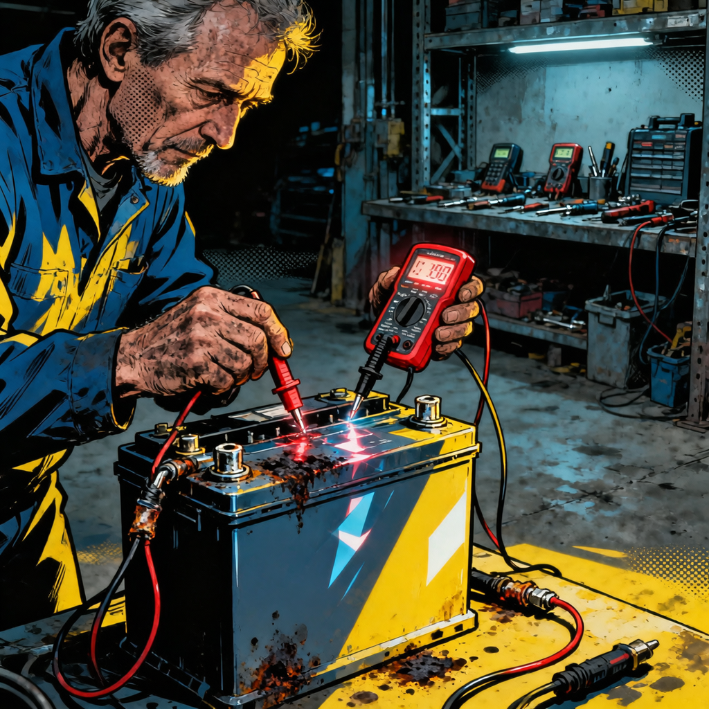
A reversed-polarity battery hookup is a fast way to turn a quick battery swap into an electrical repair job. This guide explains why it happens (often the wrong battery group or terminal layout), what typically fails (main fuse, alternator diodes, and sometimes modules), how to recover safely, and how to prevent repeat incidents. The focus is practical, step-by-step triage and verification for working technicians.
Understanding Reverse Polarity and What It Damages
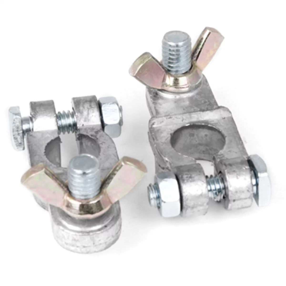
159051 W1688-2C Wilmar - Performance Tool WLMW1688-2C 2 Pc Marine Battery Terminals
Mfg: Wilmar - Performance Tool
Part #: W1688-2C
Modern vehicles are negative-ground DC systems. Swapping the battery leads reverses the polarity to every circuit. Fuses do not inherently protect against reverse polarity; they protect against overcurrent. When polarity is reversed, some semiconductor devices (diodes and transistors) conduct in ways they were never designed to, potentially shorting instantly or silently weakening.
Common outcomes after even a brief reverse-polarity connection:
- Main battery fuse or fusible link opens: Many vehicles employ a bolted 80–150 A battery fuse or fusible link at the underhood fuse/relay box. In some cases, a downstream device effectively “crowbars” to ground, rapidly blowing this fuse. That’s the best-case scenario.
- Alternator rectifier/regulator damage: The alternator’s diode trio/rectifier is extremely vulnerable. A reversed battery can short the diode pack, leaving a perpetual short on the B+ circuit or causing high AC ripple once running.
- Module damage: Any module lacking robust reverse-polarity protection is at risk—body and infotainment modules, HVAC heads, audio amplifiers, instrument clusters, and occasionally engine/transmission controllers. Severity depends on design, protection circuitry, and how long the reverse condition existed.
- Secondary effects: Melted battery clamps, vaporized small-gauge jumpers, blown smaller fuses, and scorched wiring near the battery or fuse box.
Symptoms after the event may include no power at the cabin, blown main fuse, crank/no-start, odd accessory behavior, or normal operation with hidden alternator issues. Don’t assume it’s fine just because the engine starts after you correct the battery—verify the charge system and scan all modules.
Battery Selection: Group Size, Terminal Layout, and Post Size


Reverse polarity mistakes often start with the wrong battery. Two details matter most: group size (footprint, height, and hold-down geometry) and terminal layout (which side is positive when oriented correctly). Terminals can be mirrored between visually similar group sizes. A common example: Group 24 vs. Group 24F. They look alike, but their terminal positions are flipped relative to the case. Installing a 24 where a 24F is required forces the cables to reach the wrong posts or not reach at all, encouraging a backward hookup.
Key points to verify:
- Group and orientation: Confirm via the parts catalog by year/make/model/VIN. Pay attention to the letter suffixes (e.g., 24F versus 24). For powersports, suffixes like “L” can indicate reversed terminals (e.g., YTX20 vs. YTX20L).
- Terminal polarity markings: Batteries are stamped or molded with + and − near the posts. Never rely solely on cable colors; always match the marking on the battery to the vehicle’s positive and negative leads.
- Post size difference: SAE top posts are different sizes by design—positive is larger (approx. 17.5 mm), negative is smaller (approx. 16.0 mm). If a clamp doesn’t fit cleanly, stop and re-verify polarity and group.
- Cable identification: The negative cable bonds to chassis or engine block (often a simple clamp to body and a ground strap). The positive cable feeds a distribution block/fuse box and may have a protective red cover or integrated fusible link. Trace the cable if the color is missing or both are black.
Do not improvise with shims or spacers to force a poor fit due to the wrong battery. If the clamp won’t seat correctly on the post without a shim, replace a worn clamp or use proper lead shims only after confirming the correct battery and polarity.
Immediate Recovery Steps After a Reverse-Polarity Event

If a reverse hookup occurs, the priority is to prevent additional damage and re-power the system safely.
- Disconnect safely: Key off. Remove the negative cable first, then the positive. Do not attempt to crank or “test” anything while hooked up backwards.
- Verify the correct battery: Check the catalog again for group, height, and terminal orientation. Example: Many Honda Odyssey models use Group 24F (positive on left when posts are nearest to you). If you have a 24 (positive on right), return it and get the correct 24F.
- Inspect the cables and clamps: Look for heat discoloration, melted insulation, or deformed clamps. Replace damaged parts now.
- Check the main fuse/fusible link: Locate the bolted mega fuse or battery fuse (commonly 80–150 A) in the underhood fuse box. Don’t trust visual windows alone—use a multimeter for continuity across the fuse. Replace only with the exact rating and style; never bypass or jumper.
- Isolate the alternator if in doubt: Before re-powering the vehicle, remove the alternator B+ cable from the alternator (insulate the cable end). This prevents a shorted rectifier from instantly loading the system and re-blowing the main fuse.
- Install the correct battery: Clean posts and clamps. Install with the posts oriented correctly. Tighten clamps to spec (common clamp torque ranges around 5–7 N·m / 44–62 in·lb; always follow the vehicle spec). Connect positive first, then negative.
- Initial power-up check: With the alternator still isolated, key on and observe for smoke, odor, or abnormal current draw. Verify interior power, cluster illumination, and basic functions.
- Scan all modules: Connect a scan tool and perform a full-vehicle network scan. Record and clear codes. Expect some undervoltage and communication DTCs; recheck after road test to identify persistent failures.
- Reconnect alternator and retest: Reattach the alternator B+ cable, then recheck system operation. If the main fuse opens again or heavy current draw appears, suspect a shorted alternator diode pack.
Address any blown low-amp fuses found during these steps. Replace and retest methodically; if a fuse blows immediately on key-on, isolate that branch circuit and inspect for a shorted module.
Post-Repair Electrical Diagnostics and Verification
Once the vehicle powers up correctly with the proper battery installed, verify the health of key systems.
- Charging system output: With the engine running and accessories off, measure charging voltage at the battery. Expect roughly 13.5–14.8 V depending on temperature, load, and strategy. If low or unstable, test alternator output current and field control as guided by the service manual.
- AC ripple test: A failed rectifier diode produces elevated AC ripple. Using a meter capable of AC measurement at the battery, look for less than ~100 mV AC at idle with electrical loads off. If your spec or tool differs, follow the OEM or tool standard. Excess ripple indicates alternator service.
- Main fuse integrity under load: After replacement, perform a voltage drop test across the main fuse at moderate load (headlights/high blower). Excessive drop suggests overheated or damaged contacts—replace the fuse or inspect the fusebox bussing.
- Module functionality scan: Re-scan after a short road test. Persistent DTCs for internal module faults (e.g., control head, audio amp, cluster, BCM) may indicate damage. Prioritize modules that were awake or directly powered during the reverse event.
- Parasitic draw check: After all systems sleep, total draw should typically be under 50 mA on most vehicles (consult OEM specs). If high, isolate by pulling fuses or using an amp clamp and fuse buddy to identify the culprit circuit/module.
- Ground integrity: Verify battery-to-body and body-to-engine grounds for low resistance and secure attachment. High resistance grounds amplify voltage stress on modules.
Complete platform-specific resets as needed (radio code, window/sunroof pinch-learn, EPB/steering angle calibration, idle relearn, battery registration on vehicles that require it). For vehicles with battery monitoring systems, register the replacement battery per OEM procedure.
Quick Checklist for Battery Replacements
- Confirm group size and terminal orientation by VIN/catalog (e.g., 24F vs. 24 are mirrored).
- Match battery + and − markings to the vehicle’s positive and ground cables—don’t rely on cable color alone.
- Check post sizes: if the clamp won’t seat naturally, stop and re-verify.
- Disconnect negative first; reconnect negative last.
- Inspect/clean clamps and apply protective spray after tightening to spec.
- If anything sparks, smells hot, or behaves abnormally, disconnect and re-diagnose before proceeding.
FAQs
How do I quickly tell which cable is positive if both are black?
Trace each cable: the negative cable bonds to chassis or engine block with a short ground strap and an unshielded clamp. The positive cable routes to a fuse/distribution box and may include a red cover, fusible link, or multiple branch leads. If uncertain, follow the cable paths—don’t guess.
Will a fuse protect the car from reverse polarity?
Not by design. Fuses respond to current, not polarity. In some cases a component (often alternator diodes) will short under reverse polarity and blow the main fuse, limiting damage. But many modules can be harmed before any fuse opens. Treat reverse polarity as an incident requiring inspection and testing, not as a simple fuse-replacement event.
What parts are most likely to fail after a reversed connection?
The bolted main battery fuse/fusible link, alternator rectifier/regulator, and low-amp fuses to multiple modules are common casualties. Infotainment components, audio amplifiers, HVAC control heads, and instrument clusters are frequent victims. ECM/TCM damage is less common but possible. Always verify charging system health and scan every module.
Can the starter motor be damaged or run backward?
Starter systems are relay/solenoid controlled and designed for correct polarity. With reversed polarity, the control circuits and solenoid may not energize as intended. The bigger risk is damage upstream (fuses, alternator, modules). If the starter circuit saw reverse polarity, inspect the solenoid control circuit and verify normal cranking current after correcting the battery and replacing any blown fuses.
Why didn’t the clamps fit when the battery was backward?
SAE top posts are intentionally different sizes: positive is larger than negative. If the wrong group or orientation forces you to put the negative clamp on a positive post (or vice versa), the fit will be poor. That is a built-in warning. Don’t force it or shim around the mismatch—verify the correct battery group and connect to the marked terminals.
What’s the right way to avoid this in the future?
Use the catalog by VIN to select the correct group and orientation, verify the +/− on the battery against the vehicle cables before removing the old battery, and check the clamp fit without tools before tightening. In the shop, adopt a checklist, stage your meter nearby, and don’t connect a memory saver or charger until polarity is confirmed.
Shop Paint & Finishing Tools
After cleaning up a reverse-polarity incident or replacing damaged components, you may need to restore battery trays, brackets, or engine-bay surfaces. Explore our Automotive Paint & Finishing Tools for efficient prep and refinishing.
- Surface prep: sanding blocks, DA sanders, scuff pads, and abrasives.
- Masking and protection for underhood and exterior areas.
- Primers, touch-up, spray guns, and polishing compounds for final finish.
Related Paint and Body Products
While battery polarity issues are critical for electrical systems, proper vehicle maintenance includes protecting your paint and body from corrosion and damage. Our paint and body category offers protective solutions and repair products to keep your vehicle looking pristine.
- Corrosion Prevention Coatings: Protect metal components from rust caused by battery acid leaks or terminal corrosion
- Body Filler and Touch-Up Paint: Repair cosmetic damage that may result from battery compartment incidents
- Weatherstripping and Seals: Prevent moisture and contaminants from entering engine bay and affecting paint finish
The Toolsource Technical Team blends decades of real-world automotive service experience with up-to-date technical research. Our writers collaborate with professional mechanics, shop owners, and diagnostic specialists to deliver practical, workshop-ready guidance you can trust.

Follow us on social media