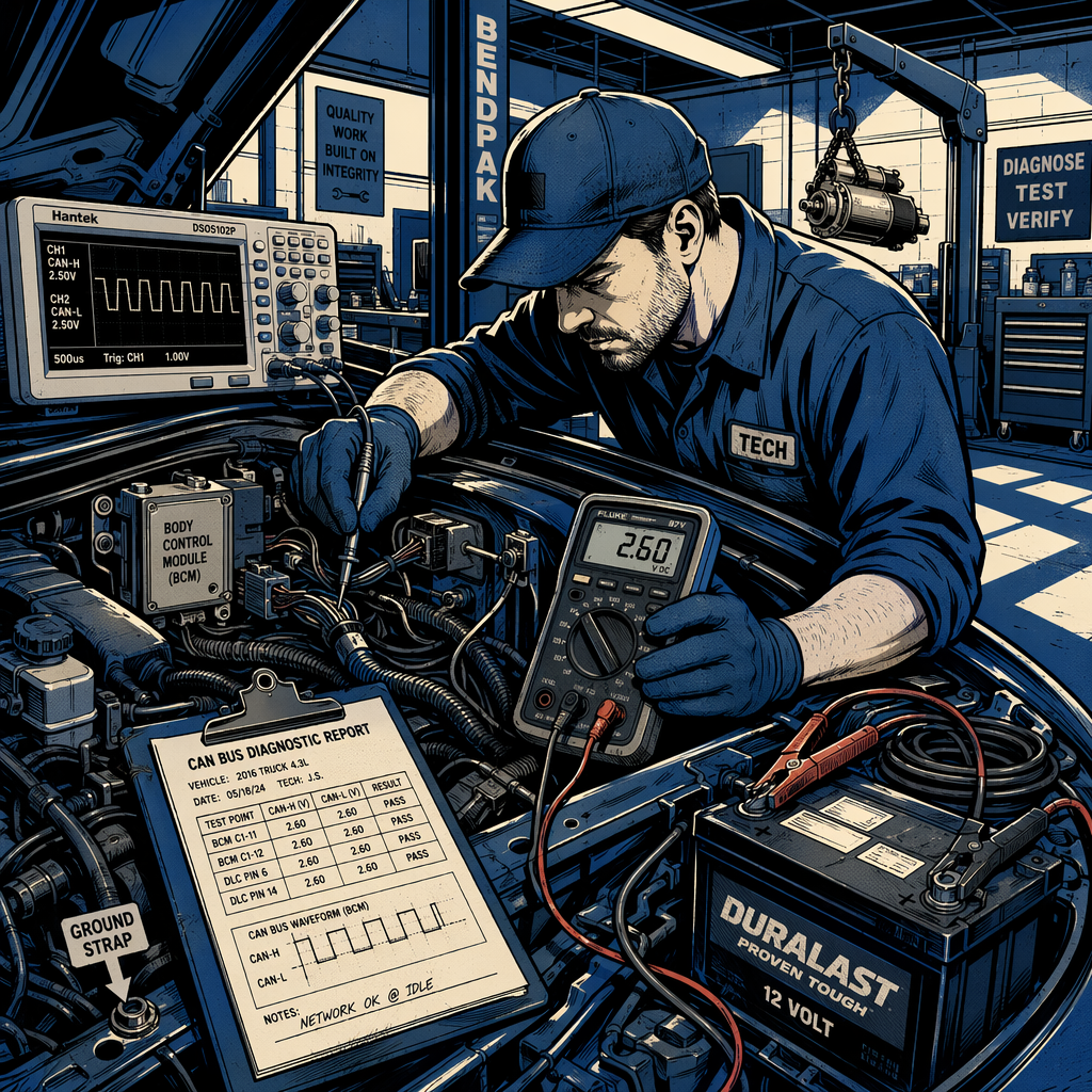
When a vehicle presents with intermittent no-start conditions accompanied by erratic data readings and no clear fault codes, you’re facing one of the most challenging diagnostic scenarios in modern automotive repair. These “possessed” level electrical issues—characterized by symptoms like phantom speed readings during cranking, intermittent starting behavior, and unexpected shutdowns—require systematic diagnostic methodology that goes well beyond traditional parts replacement strategies. This guide outlines the professional approach to diagnosing complex body control module and electrical system failures that separate competent technicians from parts changers.
Establishing a Baseline: Initial Data Collection and Documentation
Proper documentation starts the moment the vehicle enters your bay. Before touching any test equipment, establish the exact customer complaint and attempt to replicate the failure condition. For intermittent no-start issues, this means multiple start attempts while monitoring live data streams. Pay particular attention to any anomalous readings that appear during cranking—a vehicle speed sensor showing 318 mph while the engine is cranking, for instance, indicates serious communication or processing errors within the control module network.
Your initial data collection should include verification of all power and ground circuits at the starter, relay testing with proper load conditions, and battery state of charge under load. Many electrical gremlins become significantly worse under the high current draw of starter engagement, so observing system behavior during cranking is critical. Document voltage levels at key points: battery terminals, BCM power supply pins, starter relay terminals, and engine ground points. Voltage should remain stable within manufacturer specifications even during cranking; significant voltage drop or fluctuation indicates a primary circuit fault that may be causing secondary control module issues.
Create detailed notes of every test performed, every reading observed, and every conclusion drawn. These notes serve multiple purposes: they prevent you from repeating tests, they help identify patterns across multiple diagnostic sessions, and they provide justification for recommended repairs. When dealing with complex electrical issues that may require multiple visits or extensive troubleshooting time, comprehensive documentation protects both you and the customer.
CAN Bus Network Testing and Communication Verification
Modern vehicles rely on Controller Area Network (CAN) bus communication for critical functions including starting and security systems. A U1000 code (CAN bus communication error) often precedes erratic module behavior, but absence of this code doesn’t guarantee proper communication. The CAN bus network operates on voltage differentials between two twisted wires (CAN High and CAN Low), and proper testing requires more than just voltage measurements at rest.
Begin with terminating resistance testing between CAN High and CAN Low circuits. You should measure approximately 60 ohms with all modules connected (two 120-ohm terminating resistors in parallel). This confirms physical circuit integrity but doesn’t verify signal quality. The next critical step is oscilloscope analysis of the CAN bus signals during cranking and attempted starting. You’re looking for clean, well-defined square waves with proper voltage transitions. Ground noise, voltage spikes, or signal degradation during high-current events like starter engagement indicate either poor grounding or a module pulling the network down.
Test individual module communication by monitoring specific data PIDs from each controller. The body control module (BCM) should consistently report accurate sensor data—when it reports impossible values like triple-digit speeds during cranking, you’ve identified either a faulty BCM or corrupted input to the BCM. Isolate the cause by disconnecting suspect sensors (vehicle speed sensor, transmission output speed sensor) one at a time while monitoring the data stream. If the erroneous reading persists with sensors disconnected, the BCM itself is generating false data.

Ground Circuit Integrity and Power Distribution Testing
Electrical issues that worsen during cranking frequently trace back to inadequate ground paths. The high current draw of the starter motor—often 200-300 amps—can expose marginal ground connections that function adequately under normal loads. These ground faults create voltage differentials between modules and sensors, leading to erratic data and communication failures.
Perform voltage drop testing on all major ground paths with the starter engaged. Connect your meter negative lead to battery negative and probe engine block grounds, body grounds, and BCM ground terminals. Any reading above 0.2 volts during cranking indicates excessive resistance that will cause system instability. Pay special attention to engine-to-chassis ground straps and battery negative cable connections—these are high-failure points that create exactly the symptoms described in complex electrical cases.
Similarly, test power distribution under load. The power distribution center (fuse box) that houses the starter relay should show stable voltage at all terminals during cranking. If you find evidence of heat damage, burned terminals, or bare wire insulation at the starter relay, you’ve likely found a contributing factor. However, don’t stop there—ask why that relay overheated. Is the starter drawing excessive current? Is there a poor connection creating high resistance? Treat symptoms as diagnostic clues, not final answers.
Starter Circuit Analysis and Current Draw Testing
An overlooked aspect of intermittent no-start diagnosis is the starter motor itself. A starter with internal shorts or failing components can draw excessive current, create electrical noise that propagates through the vehicle’s electrical system, and even backfeed interference through control circuits. This is particularly relevant when you observe erratic module behavior specifically during cranking attempts.
Conduct a full starter current draw test using an inductive ammeter. Compare your readings to manufacturer specifications—typically 150-250 amps for a healthy starter, though this varies by application. Excessive current draw indicates internal starter problems that may be creating the electrical noise affecting your BCM and other modules. Consider temporarily isolating the starter’s electrical load by disconnecting the main starter power cable (with the terminal properly insulated) and using a separate vehicle with jumper cables to power only the starter motor and engine ground. If the vehicle’s electrical system behaves normally when the starter current is isolated, you’ve confirmed the starter is introducing noise into the system.
Additionally, verify proper operation of the starter relay and its control circuit from the BCM. Using a lab scope or digital multimeter with recording capability, monitor the BCM’s output signal to the starter relay during key-on and crank attempts. The signal should be clean and consistent. If the BCM fails to send the start signal, or if the signal is intermittent or malformed, the fault lies in the BCM itself rather than downstream components.
Body Control Module Diagnosis and Replacement Decision
After systematic testing eliminates power supply issues, ground faults, CAN bus physical problems, and starter circuit defects, the BCM becomes the prime suspect—especially when you’ve documented erratic data output from the BCM that cannot be explained by sensor inputs. However, BCM replacement is not a simple swap; these modules are typically VIN-programmed and require dealer-level scan tools for initialization.
Before committing to BCM replacement, inspect the module’s physical location and condition. In many vehicles, the BCM resides in areas vulnerable to water intrusion—passenger kick panels, under-dash locations near HVAC drain paths, or behind access panels that can leak during heavy rain. Check for signs of water damage, corrosion on connectors, or moisture in the module housing. A clogged HVAC drain or compromised windshield seal can introduce water that causes intermittent BCM failures matching your symptoms.
When the decision tree points to BCM replacement, set clear expectations with the customer. Present the diagnostic findings that led to this conclusion, acknowledge that complex electrical issues sometimes have multiple failure points, and establish a firm budget ceiling before proceeding. The technician who spent hours documenting every test and reading has earned the right to make an educated diagnosis, but the customer needs to understand that electrical diagnosis sometimes requires an iterative approach—replace the most likely failed component, retest, and reassess.
Diagnostic Checklist for Complex Electrical No-Start Conditions
- Verify customer complaint with multiple start attempts while recording live data
- Test battery voltage and state of charge; load test to verify capacity under cranking load
- Measure voltage drop on all power and ground circuits during cranking (under 0.2V acceptable)
- Check CAN bus terminating resistance (should read approximately 60 ohms)
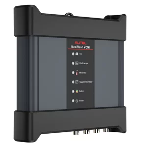
- Perform oscilloscope analysis of CAN bus signals during cranking for noise or degradation
- Monitor BCM data output for erroneous readings (impossible speed values, etc.)
- Disconnect vehicle speed sensors to isolate whether false readings originate in BCM
- Inspect starter relay and power distribution center for heat damage or poor connections
- Conduct starter current draw test; compare to specifications
- Verify BCM starter relay control signal with scope during crank attempts
- Inspect BCM location for water intrusion, check connectors for corrosion
- Document every test, reading, and conclusion for pattern analysis and customer communication
When to Walk Away: Setting Diagnostic Limits
Not every vehicle is worth saving. When diagnostic time exceeds the vehicle’s value, or when you’ve reached a point where multiple expensive modules may need replacement without certainty of success, have an honest conversation with the customer about their options. The sunk cost fallacy causes customers to throw good money after bad; your job includes providing perspective on when repair costs become irrational.
Certain vehicle platforms—particularly those from manufacturers with documented widespread electrical issues—reach a point where systemic problems make reliable repair nearly impossible. If you’re diagnosing the second or third catastrophic electrical failure on the same vehicle, recommend the customer cut their losses. Your reputation benefits more from honest advice than from chasing profitable but ultimately futile repairs.
However, when you’ve conducted systematic diagnosis, documented your findings, and arrived at a logical conclusion like BCM replacement, stand behind your diagnosis. Complex electrical issues test every technician’s skills and patience. The difference between a parts changer and a diagnostician is the methodology: parts changers guess, diagnosticians test, document, eliminate variables, and follow the evidence to a conclusion.

Frequently Asked Questions
Why do electrical problems get worse during cranking?
Starter motors draw 200-300 amps, which can expose marginal ground connections and power supply issues that don’t appear under normal loads. This high current draw can also create voltage fluctuations and electrical noise that affect sensitive control modules, making latent problems become apparent failures during starting attempts.
Can a bad starter motor cause BCM problems?
Yes. A starter with internal shorts or excessive current draw can generate electrical noise that propagates through the vehicle’s electrical system, potentially corrupting data on the CAN bus network and causing erratic module behavior. Always test starter current draw and consider isolating the starter circuit when diagnosing intermittent electrical issues that worsen during cranking.
What does it mean when a BCM shows impossible sensor readings?
When a body control module reports values like 318 mph vehicle speed during cranking with the vehicle stationary, it indicates the BCM is either receiving corrupted input signals or internally generating false data. Disconnect the relevant sensors—if the false readings persist, the BCM itself is faulty. If readings normalize, trace the sensor circuit for shorts or interference.
How do I test CAN bus communication properly?
Start with terminating resistance measurement between CAN High and CAN Low (should be approximately 60 ohms). Then use an oscilloscope to observe signal quality during operation, looking for clean square waves without noise or voltage anomalies. Monitor specific data PIDs from individual modules to verify each controller is communicating properly on the network.
Should I replace a BCM based on diagnostic evidence or wait for a fault code?
Many complex electrical failures don’t set specific fault codes because the BCM itself is malfunctioning—it can’t accurately report its own failure. When systematic testing eliminates all other variables and evidence points to the BCM (erratic data output, inability to control outputs properly, intermittent communication), replacement is justified even without a stored code. Proper documentation of your diagnostic process supports this decision.
What’s the best way to avoid being “snowblind” during long diagnostic sessions?
When a vehicle has consumed hours of diagnostic time without resolution, step away completely. Work on a different vehicle, take a break, and return with fresh perspective. Review your notes from the beginning as if you’re seeing the vehicle for the first time. Sometimes technicians develop tunnel vision after extended troubleshooting; resetting your mental state often reveals overlooked details or alternative approaches.
Recommended Diagnostic Tools
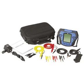
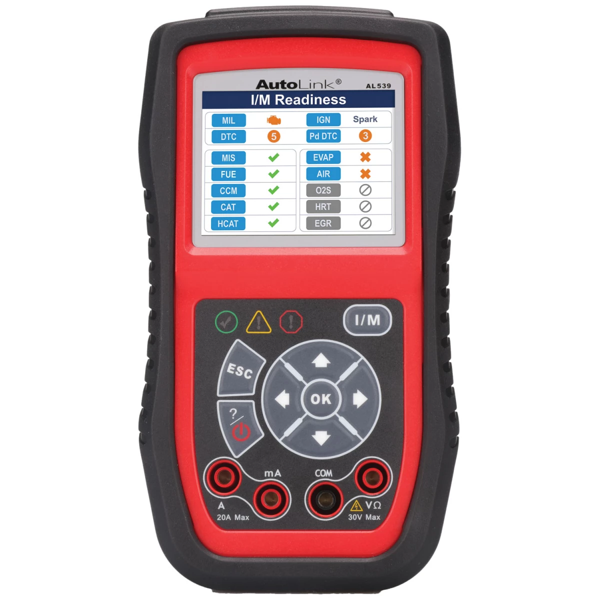
Diagnosing complex electrical no-start conditions demands proper equipment. Explore our selection of Automotive Diagnostic Tools to ensure you have the instruments necessary for systematic testing and accurate results.
- Oscilloscopes and lab scopes for CAN bus signal analysis and voltage measurements
- Inductive ammeters and digital multimeters for current draw and voltage drop testing
- Scan tools and data recorders for live data stream monitoring and fault code retrieval

The Toolsource Technical Team blends decades of real-world automotive service experience with up-to-date technical research. Our writers collaborate with professional mechanics, shop owners, and diagnostic specialists to deliver practical, workshop-ready guidance you can trust.


Follow us on social media