Intermittent electrical faults are the comebacks nobody wants: a customer describes a problem that isn’t happening when the car is on the lift, codes that set once and never again, and connectors that look fine until you touch them the wrong way. There’s no single trick that solves every intermittent fault, but there is a repeatable workflow that narrows the search fast and keeps you from throwing parts at a problem. This guide walks through that workflow in the order most techs actually use it, from confirming the complaint to tracing the wire that’s actually at fault.
Confirm the Complaint Before You Touch Anything
Before pulling a single connector, get as much detail from the customer or the write-up as possible. Ask when the fault happens: cold starts, hitting bumps, after rain, only at highway speed, only when the AC is on. Each of these points to a different failure mode—thermal expansion in a connector, a chafed wire flexing against a bracket, moisture intrusion, or a load-dependent voltage drop. If the vehicle has stored codes, pull freeze frame data before clearing anything. Freeze frame conditions (RPM, load, coolant temp, time since start) often match the customer’s description and confirm you’re chasing the right circuit.
If you can reproduce the fault on demand—even inconsistently—you have a massive advantage. Road test with a scan tool in the car if the complaint is speed- or vibration-related. If it only happens with electrical load stacked (headlights, blower, rear defrost, AC all on), replicate that load in the bay before you start testing.
Check the Basics: Battery, Grounds, and Main Connections
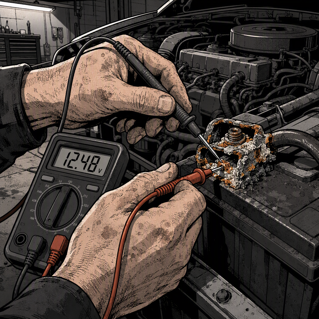
A surprising percentage of “random” electrical gremlins trace back to a weak battery, a corroded terminal, or a loose engine or body ground strap. Before diving into a specific circuit, do a quick battery and charging system check: load test the battery, verify charging voltage at idle and at 2000 RPM, and inspect both battery terminals and cable ends for corrosion under the insulation, not just at the visible clamp. Corrosion often creeps up inside the cable and isn’t visible until you cut back the jacket.
Next, check the major ground straps—engine-to-body, engine-to-frame, and body-to-frame. A ground with even 0.2-0.3V of resistance under load can cause flickering lights, erratic gauge readings, module communication faults, and phantom sensor codes that have nothing to do with the sensor itself. Clean and re-torque these before you assume the fault is deeper in a specific circuit.
No products found for "automotive multimeter with min/max recording"
Isolate the Circuit with a Multimeter and Scan Tool
Once the basics check out, move to the specific circuit. A scan tool with live data and bi-directional controls lets you watch sensor voltages and module status in real time, which is far more useful than a code alone for an intermittent problem. Graph the suspect PID and watch for dropouts or spikes correlated with the fault. A code that says “circuit intermittent” or “signal implausible” is telling you the same thing your multimeter will show: a voltage that’s briefly out of range.
For circuit-level testing, a multimeter with a min/max recording function is essential—intermittent faults by definition don’t sit still long enough for a static reading. Set min/max, then wiggle-test or road-test while it’s connected, and check the recorded extremes afterward. A voltage drop test across a connector under load (not with the circuit open) will reveal resistance that a simple continuity check on a cold, static bench will miss every time.
Wiggle Testing and Wire Tracing for Physical Faults
If live data and voltage drop tests point to a specific circuit but not a specific location, it’s time for a physical wiggle test. With the multimeter or scan tool live, work down the harness methodically—starting at the connector nearest the symptom and moving outward—flexing, tapping, and applying light pressure at connectors, harness routing points, and anywhere the wire passes through a grommet, over an edge, or near a moving component (motor mounts, suspension travel, hood hinges, door jambs).
Pay close attention to any point where the harness crosses a heat source, rubs against a bracket, or flexes repeatedly, like door and hatch harnesses. Chafe-through shorts to ground and open circuits from repeated flexing are two of the most common physical causes of intermittent faults, and both will usually respond to a wiggle test even if they don’t show up on a static check.
Document each test point as you go—even negative results. On a hard-to-catch fault, you may be working the diagnosis over more than one visit, and a clear record of what’s already been ruled out saves time on the second attempt.
Common Culprits Worth Checking Every Time
Certain failure points show up disproportionately often in intermittent-fault diagnosis, and it’s worth checking them early even if they aren’t the obvious suspect:
- Corroded or spread connector pins, especially in engine bay and underbody connectors exposed to road salt and moisture
- Ground straps and body grounds, particularly on vehicles with aftermarket accessories added to factory ground points
- Chafed harness sections at grommets, hinges, and anywhere near sharp sheet metal edges
- Aftermarket wiring—remote starts, stereo installs, trailer wiring, and alarm systems—tapped into factory circuits
- Fuse box and relay contacts with heat damage or corrosion, which can cause voltage drop under load without an open circuit
- Module connectors that have been disturbed during other repairs and not fully seated
When to Pull Wiring Diagrams and Escalate
If basic checks and wiggle testing don’t isolate the fault, stop guessing and pull the wiring diagram. Trace the actual circuit path for the affected component, including shared grounds, splices, and any modules the signal passes through. Many intermittent faults that look like a bad sensor are actually a shared ground or splice point affecting multiple circuits—if two seemingly unrelated systems fault at the same time, that’s a strong clue to look for a shared connector or ground.
For faults that won’t reproduce in the shop, a data logger or scan tool with a longer recording window that the customer can drive with is often the only way to capture the fault event. Set the logger to trigger on the specific code or parameter and have the customer note the conditions when it happens. This turns a guessing game into a targeted repair once the data comes back.
Quick Diagnostic Checklist
- Confirm the complaint and note the conditions (temperature, load, road surface, weather)
- Pull freeze frame data before clearing any codes
- Load test the battery and check charging voltage under load
- Clean and re-torque main ground straps
- Voltage drop test suspect circuits under load, not just continuity at rest
- Wiggle test connectors and harness routing points while monitoring live data
- Check for shared grounds or splices if multiple systems fault together
- Pull wiring diagrams before replacing parts on a guess
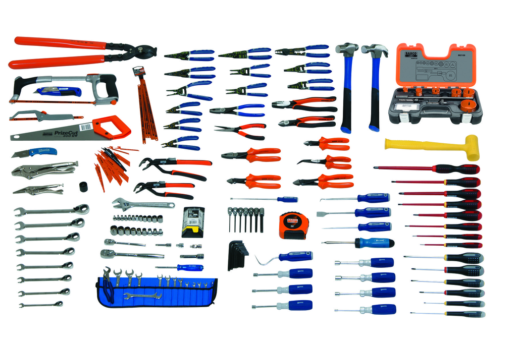
Electrical Maintenance Service Set With Tool Box
Mfg: J.H. Williams
Part #: JHWELECTRICALTB
Frequently Asked Questions
Why do intermittent faults often disappear when I connect a scan tool or multimeter?
Disturbing a connector to attach test leads can temporarily improve a marginal connection, masking the fault. Test at connectors adjacent to the suspect one, and use non-invasive methods like current clamps or back-probing where possible.
How long should I let min/max recording run before concluding there’s no fault?
Long enough to reproduce the reported conditions at least once, ideally several times. If the customer says it happens on cold starts, a warm-shop static test won’t capture it—road test or let the vehicle sit overnight if needed.
Is a voltage drop test always better than a continuity check?
For live circuits, yes. Continuity checks are done with no current flowing and can pass even when a connection has enough resistance to fail under real load. Always test voltage drop with the circuit powered and under its normal load.
What’s a normal amount of voltage drop across a connector or ground?
As a general guideline, keep drops under roughly 0.1V per connector and under about 0.3-0.5V for a full ground path under load, though always check the manufacturer’s specification for the specific circuit.
Should I replace a module if it’s throwing an intermittent communication code?
Not without ruling out the wiring first. Communication codes are frequently caused by a poor ground, corroded connector, or chafed CAN bus wire rather than a failed module—module replacement should be a last resort after the harness and grounds are confirmed good.
How do I handle a fault I truly cannot reproduce in the shop?
Use a data logger set to trigger on the specific fault parameter and send the customer out with it. Capturing real-world data during an actual fault event is more reliable than guessing based on a static bench test.
Shop Automotive Diagnostic Tools
The workflow in this guide relies on quality tools—a multimeter with min/max recording, a scan tool with live data and graphing, and data loggers for capturing hard-to-reproduce faults. Explore our Automotive Diagnostic Tools selection for everything from basic multimeters to advanced scan tools.
- Multimeters with min/max recording and voltage drop measurement
- Scan tools with live data, graphing, and freeze frame capture
- Data loggers for remote diagnostics of intermittent faults

The Toolsource Technical Team blends decades of real-world automotive service experience with up-to-date technical research. Our writers collaborate with professional mechanics, shop owners, and diagnostic specialists to deliver practical, workshop-ready guidance you can trust.


Follow us on social media