Every service writer has fielded the call: a customer put a laser level or string line under their truck, found the driveshaft isn’t perfectly straight, and is convinced something’s broken. Nine times out of ten, nothing is. Universal joints are designed to run at an angle, and a driveshaft that looks “crooked” between the transmission and the axle is frequently doing exactly what the factory intended. The real diagnostic work isn’t confirming the shaft is off-center — it’s determining whether the operating angle, the phasing, or the balance is actually causing a problem. Here’s how to work through it the way an experienced driveline tech does.
Why U-Joints Need an Angle, Not a Straight Line
A U-joint (universal joint) is a cross-and-bearing assembly that lets two shafts rotate at an angle to each other. The needle bearings inside each cap only roll and redistribute grease when the joint is actually articulating. If a shaft ran perfectly straight through a joint, the cross would sit static inside the bearing caps — the needles would stop rotating, grease would get pushed out of the load zone, and the bearing race would develop a flat spot (a wear pattern sometimes called brinelling) exactly where the load sits. That flat spot eventually turns into play, then noise, then failure.
This is why driveline engineers deliberately build in a working angle, usually in the 2-10° range depending on the joint size and application, and why transmissions aren’t bolted in dead-center with the rear axle. The transmission output and the pinion flange are rarely in the same plane; the U-joints exist specifically to accommodate that offset and the vertical travel of the suspension. A driveshaft with zero angle at the joints isn’t “more correct” — it’s set up to wear out the bearing caps prematurely and will often produce its own vibration, since a joint running too straight doesn’t transmit rotational velocity smoothly either.
Diagnosing Driveshaft Vibration: Angle, Phase, or Balance
When a customer complains about a shake or vibration that changes with speed or load, don’t jump straight to “bad U-joints” or “bad alignment.” There are three distinct and commonly confused causes, and they call for different fixes:
Operating angle problems show up as vibration that’s often speed-related and can worsen under acceleration or deceleration. This happens when the angle at one joint is too steep, too shallow, or when the angles at each end of the shaft aren’t complementary (the industry term is the angles should be equal and opposite, or at minimum within about 1° of each other, so the velocity fluctuations introduced by one joint are canceled out by the other).
Phasing problems happen on two-piece or double-cardan shafts when the yokes at each end aren’t clocked correctly relative to each other. An out-of-phase shaft can look visually straight and still produce a nasty vibration because the velocity pulses from each joint reinforce instead of cancel. This is a rotational/clocking issue, not an angle issue, and it’s commonly introduced when a shaft is disassembled for U-joint replacement and reassembled incorrectly.
Balance problems feel different — typically a vibration that’s smooth and speed-proportional with no load sensitivity, often from undercoating buildup, a bent tube, mud/debris packed on the shaft, or a missing balance weight. These generally require shaft removal and a trip to a driveline shop with a balancer.
A quick field test: if the vibration changes noticeably between coasting, steady throttle, and acceleration, suspect angle or phasing. If it’s consistent regardless of drivetrain load and scales cleanly with road speed, suspect balance.
[PRODUCT_SEARCH: driveshaft angle finder tool]


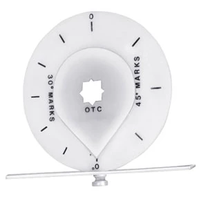
Torque Angle Gauge for Precise Fastener Tightening
Mfg: OTC Tools and Equipment
Part #: 7415
Checking and Correcting U-Joint Operating Angles
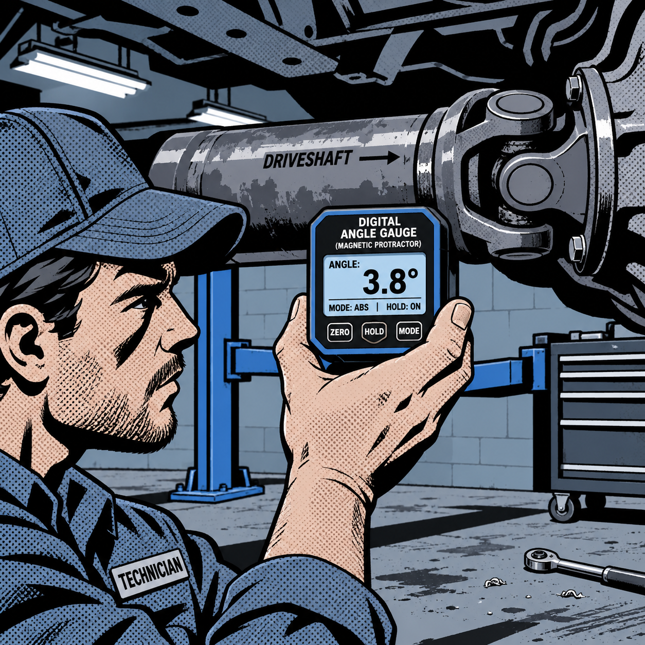
Measuring operating angle correctly requires a digital angle gauge (a magnetic protractor or dedicated driveline angle finder) at four points: the transmission output/slip yoke, the front of the driveshaft, the rear of the driveshaft, and the pinion flange. Steps:
- Support the vehicle at normal ride height — on the ground or on a drive-on lift, not hanging on jack stands, since suspension droop changes every angle in the system.
- Measure the transmission’s output shaft angle relative to level.
- Measure the driveshaft’s angle.
- Measure the pinion/differential angle.
- Calculate the working angle at each joint (the difference between the shaft angle and the component it connects to) and compare front to rear. They should be close to equal and opposite, and each joint should fall within the manufacturer’s recommended working angle range — commonly cited as 1-3° minimum to keep the bearings lubricated and under 15° before a single joint is overstressed.
If the angles are outside spec, the fix is almost always at the axle end: adjustable upper or lower control arms, shims, or a pinion-angle-correcting bushing on leaf-spring trucks. Don’t try to fix a pinion angle problem by shimming the transmission mount unless the transmission itself has shifted from a broken mount — that just moves the problem around.
Driveshaft Phasing — What It Is and Why It Matters
On a one-piece shaft, phasing is set at the factory and can’t be adjusted — the yokes are welded in a fixed relationship. On a two-piece shaft with a center carrier bearing, or any shaft that’s been cut, re-tubed, or had a slip yoke replaced, phasing can absolutely be set wrong during reassembly. The front and rear yokes need to be clocked in the same rotational plane. If a shop rebuilt a shaft and the vibration got worse rather than better, out-of-phase yokes are one of the first things to check before chasing angle or balance. This is also the scenario behind shafts that “look straight” by eye or laser line but still vibrate badly — phasing is invisible to a straightedge because it’s a rotational alignment, not a linear one.
Lift Kits, Lowered Trucks, and Double-Cardan Joints
Any suspension lift or lowering job changes the transmission-to-pinion geometry and pushes the operating angles outside the range a single U-joint handles well. As a rule of thumb, once the required angle exceeds roughly 15°, a standard single Cardan joint will introduce enough velocity fluctuation to cause a noticeable vibration no matter how well everything else is set up. That’s the point to move to a double Cardan (CV-style) joint, which uses a centering ball and two joints working together to cancel out that fluctuation.
On many solid-axle trucks and Jeeps lifted 3.5″ or more, a slip yoke eliminator kit paired with a CV driveshaft is the standard correction — it relocates the joint and restores acceptable geometry instead of asking a single joint to absorb an angle it wasn’t built for. Skipping this step on a heavily lifted truck is one of the most common causes of a vibration that no amount of U-joint replacement or balancing will fix.
Signs of U-Joint Failure and Inspection Routine
U-joints fail gradually, and the early symptoms are easy to blame on other components (which is exactly why they get missed on transmission and driveline inspections for years). Check for:
- A clunk on shifting from park to drive/reverse, or on initial takeoff
- A squeak at low speed that changes with engine RPM but not road speed (dry joint)
- Vibration that appears or worsens at highway speed
- Visible rust-colored grease residue flung around the joint — often misread as a leak, but frequently just grease being slung by a joint that’s doing its job at the correct operating angle
- Play detectable by hand: with the shaft supported, grab each side of a joint and try to twist in opposite directions — any looseness means it’s time to replace
A driveshaft that drops at highway speed is not a minor inconvenience — it can destroy a transfer case, take out a transmission tail housing, or become a projectile. If a joint shows any detectable play, it should be replaced immediately, not monitored.
Quick Diagnostic Checklist
- Support vehicle at ride height before measuring anything
- Measure angles at trans output, driveshaft, and pinion with a digital angle gauge
- Confirm front/rear joint angles are equal and opposite, within spec
- Hand-check each U-joint for play; replace at the first sign of looseness
- Verify phasing on any two-piece or rebuilt shaft
- Add a double Cardan/CV joint if calculated angle exceeds ~15°
- Rule out balance (mud, bent tube, missing weight) if vibration is load-independent
[PRODUCT_SEARCH: driveline and U-joint service tools]
Frequently Asked Questions
Is it normal for a driveshaft to not look perfectly straight?
Yes. Transmissions and axles are rarely in the same plane, and U-joints are designed to operate at an angle so the needle bearings keep rotating and distributing grease. A visibly offset shaft that drives smoothly is usually correct, not damaged.
What happens if a U-joint runs perfectly straight with no angle?
The needle bearings stop moving inside the cap, grease stops circulating in the load zone, and the bearing race develops a flat spot from constant load in one position. This accelerates wear and can itself cause vibration.
How much U-joint angle is too much?
Most single Cardan joints are happiest in the 2-10° range and start struggling above 15°. Beyond that, plan on a double Cardan (CV) joint to cancel out the velocity fluctuation a single joint can’t handle.
My driveshaft looks straight but still vibrates — what’s wrong?
Check phasing before anything else, especially if the shaft was recently serviced. Yokes clocked incorrectly during reassembly cause vibration that has nothing to do with visible alignment.
Can I fix pinion angle by shimming the transmission mount?
Only if the transmission mount has failed and let the trans shift position. Otherwise, pinion angle corrections belong at the axle — control arms, shims, or angle-correcting bushings — not at the transmission.
Does a lift kit always require a new driveshaft setup?
Not always, but any lift over a few inches pushes the operating angle out of normal range. At that point a slip yoke eliminator kit and CV driveshaft is the standard fix rather than running a single joint past its design limit.
Driveshaft & U-Joint Tools
Diagnosing U-joint wear and measuring operating angles requires the right specialty equipment. Check our Drive Shaft & U Joint selection for angle gauges, service tools, and replacement components.
- Digital angle gauges and driveline angle finders for operating angle measurement
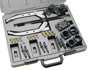
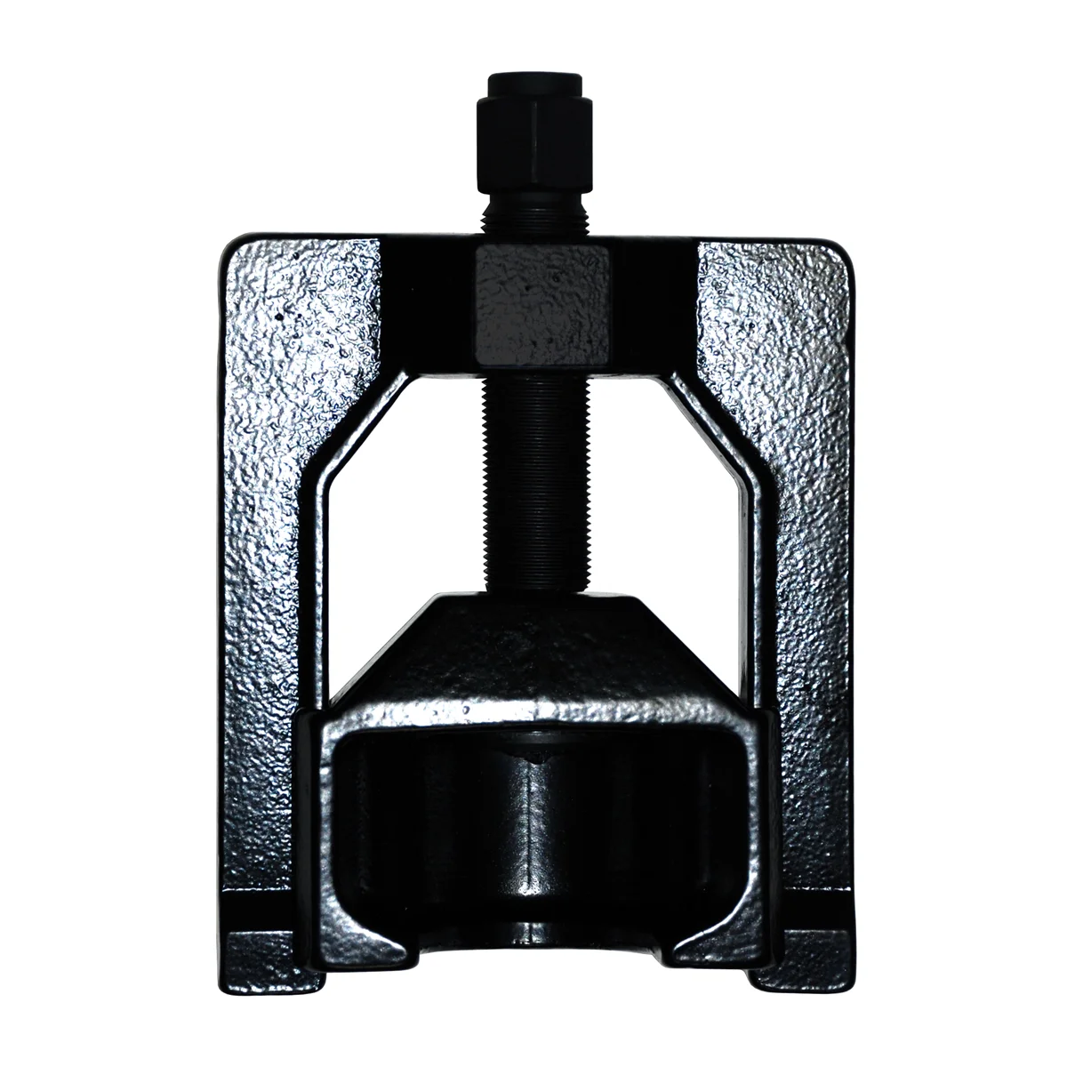
- U-joint service equipment: presses, pullers, and bearing removal tools
- Replacement U-joints and CV driveshaft assemblies

The Toolsource Technical Team blends decades of real-world automotive service experience with up-to-date technical research. Our writers collaborate with professional mechanics, shop owners, and diagnostic specialists to deliver practical, workshop-ready guidance you can trust.


Follow us on social media