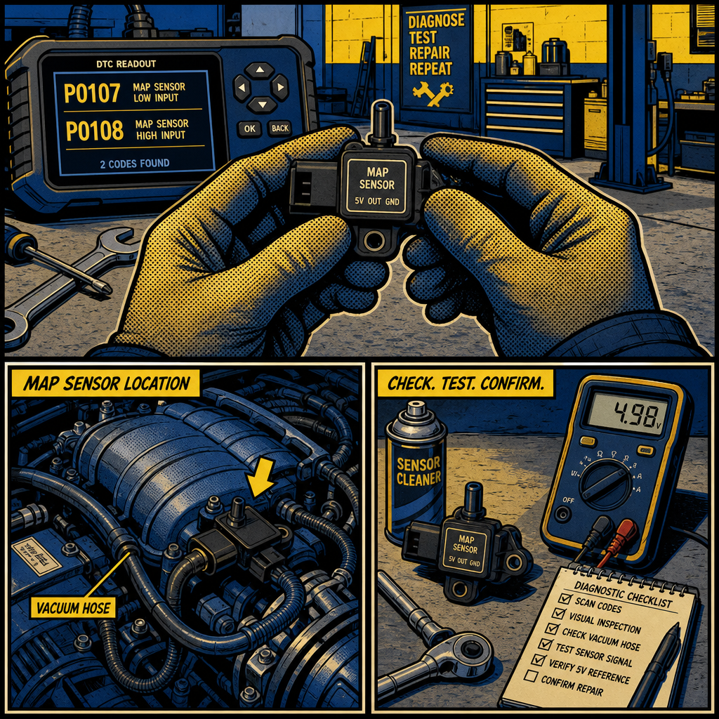
The manifold absolute pressure (MAP) sensor is critical in your vehicle’s engine management system. This small sensor provides the ECU real-time intake manifold pressure data for precise air density and engine load calculation. When it fails or installs incorrectly, you’ll face rough idle, poor fuel economy, hesitation, and codes P0107/P0108. Understanding MAP sensor location, diagnosis, and when to clean versus replace can save diagnostic time and prevent unnecessary parts replacement.
MAP vs MAF Sensors: Understanding the Difference
The most common mistake is confusing MAP with mass airflow (MAF) sensors. While both provide airflow data to the ECU, they work on different principles and aren’t interchangeable.
How manifold absolute pressure sensors work differently from mass airflow sensors
A MAP sensor measures absolute pressure inside the intake manifold, generating a 0.5-4.5 volt signal corresponding to manifold vacuum and atmospheric pressure. At idle (high vacuum), it outputs low voltage; at wide-open throttle (minimal vacuum), it outputs higher voltage. The ECU calculates air mass using this pressure reading plus intake air temperature and RPM.
MAF sensors directly measure air mass flowing into the engine using a hot-wire or hot-film element. Air cooling the heated element correlates airflow mass to the required current. MAF sensors provide direct measurement rather than calculated values, which is why many modern engines use them instead of MAP sensors.
The key difference: MAP sensors measure pressure (requiring calculation for air mass), while MAF sensors measure actual air mass directly. Some vehicles use both. According to SAE International, speed-density systems using MAP sensors can be equally accurate when properly calibrated.
Visual identification guide: telling MAP and MAF sensors apart

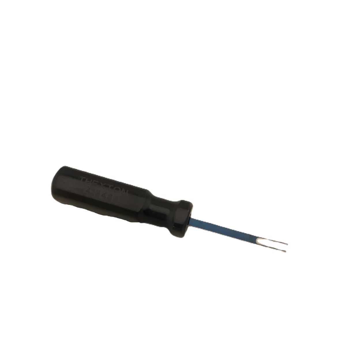
Extended Tyco and Bosch Duel Tab (Injector/Sensors)
Mfg: Thexton Toolworx LLC
Part #: 414517
Micro Tyco and Bosch Duel Tab (Injector/Sensors)
Mfg: Thexton Toolworx LLC
Part #: 413483
MAP sensors are small, cylindrical or rectangular components mounted on the intake manifold or connected via vacuum hose. They have a three-wire connector (signal, ground, 5-volt reference) and measure 1-3 inches long with a vacuum port nipple or mounting flange with O-ring seal.
MAF sensors are larger tubular components in the intake air duct between the air filter and throttle body. They measure 4-8 inches long with a 4-6 wire connector and contain the sensing element suspended in the airflow—you can often see the hot-wire element.
Location is usually definitive: if in the intake duct before the throttle body, it’s a MAF; if mounted on the intake manifold after the throttle body, it’s a MAP.
Why confusing the two leads to costly mistakes
Replacing a MAP when you actually have a faulty MAF wastes money and time. Symptoms overlap (poor idle, hesitation, check engine lights), but diagnostic approaches differ significantly. Never attempt switching between MAP-based speed-density and MAF systems—this requires complete ECU reprogramming.
Optimal MAP Sensor Location and Installation
Proper MAP sensor placement is crucial for accurate readings. Wrong placement causes pressure pulses, erratic signals, and poor engine performance even with a new sensor.
Why positioning near the throttle body beats mounting near the cylinder head
The intake manifold experiences significant pressure pulses as intake valves open and close, most intense near the cylinder head. Mounting a MAP sensor too close exposes it to rapid fluctuations representing individual cylinder events rather than average manifold pressure.
Positioning near the throttle body or in a plenum area provides stable, averaged pressure reading. The larger plenum volume dampens individual cylinder pulses, giving the ECU consistent overall engine load signals.
Using Y-connectors and hoses to balance pressure pulses across cylinders
When your manifold lacks a central plenum, tapping a single runner gives cylinder-specific pulses. Connect multiple runners using vacuum hoses and Y-connectors before routing to the MAP sensor. For four-cylinder engines, connect opposite cylinders (1 and 3, or 2 and 4). For six-cylinder engines, connect three runners spaced evenly in firing order.
Use vacuum-rated hose (3/16 to 1/4 inch diameter) and keep total hose length under 24 inches to minimize response lag.
Vehicle-specific manifold design considerations before installation
Research your specific engine’s intake characteristics before drilling your manifold. Turbocharged and supercharged applications require MAP sensors capable of reading positive pressure (boost), not just vacuum. Standard naturally aspirated MAP sensors read 0-15 psi absolute; forced induction requires sensors reading 30-45 psi or higher.
On custom manifolds, avoid placing the sensor where it collects oil mist, fuel vapor, or water. The sensor port should face upward or sideways, never downward where condensation accumulates.
Extended Tyco and Bosch Duel Tab (Injector/Sensors)
Mfg: Thexton Toolworx LLC
Part #: 414517
ID: 386522

Decoding P0107 and P0108 Error Codes
These codes relate to MAP sensor circuit issues, but they don’t automatically mean you need a new sensor.
What P0107 and P0108 actually indicate
P0107 (“Manifold Absolute Pressure Circuit Low Input”) means the MAP sensor signal voltage is lower than expected—typically below 0.25 volts when it should read atmospheric pressure (around 4.5 volts) with the key on, engine off.
P0108 (“Manifold Absolute Pressure Circuit High Input”) is the opposite: sensor signal reads higher than physically possible—often constant 4.8-5.0 volts regardless of pressure changes.
Both codes indicate an out-of-range signal, but don’t specify whether the problem is the sensor, wiring, connector, or ECU. Proper testing requires isolating each component before replacing parts.
Step-by-step diagnostic flowchart
For P0107 (Low Input):
- Key on, engine off: Check MAP sensor voltage (should read 4.0-5.0V)
- If below 0.5V: Check for short to ground in signal wire
- Disconnect sensor: Does voltage at ECU connector rise to 5V? If yes, sensor is shorted; if no, wiring fault
- Check 5-volt reference wire (should be 4.8-5.2V with sensor disconnected)
- Check ground circuit (should have less than 0.1V resistance to battery negative)
For P0108 (High Input):
- Key on, engine off: Check MAP sensor voltage (should read 4.0-5.0V)
- If constant 5.0V: Check for open circuit in ground wire
- Start engine: Voltage should drop to 1.0-2.0V at idle (varies by altitude)
- If voltage doesn’t change with engine running: Check for vacuum hose blockage or disconnection
- Apply vacuum manually: If voltage doesn’t drop proportionally, sensor is faulty
Use a digital multimeter with at least 0.01-volt resolution for accurate readings.
Why these codes don’t always require sensor replacement
In professional shops, P0107 and P0108 codes result in actual sensor replacement less than 40% of the time. Common non-sensor causes include corroded connector pins, broken ground wires, kinked vacuum hoses, chafed signal wires, and water intrusion. Always perform complete circuit testing before condemning the sensor—the three-wire circuit and connector are more vulnerable to environmental damage than the sensor itself.
Cleaning vs Replacement: When to Do Each
Cleaning rarely fixes MAP sensor problems and can make things worse.
When MAP sensor cleaning is effective and when it’s unnecessary
MAP sensors can become contaminated with oil vapor from crankcase ventilation, carbon from EGR, or dirt from damaged air filters. However, unlike MAF sensors, MAP sensors have their sensing element protected inside a sealed chamber—only the pressure port is exposed.
Cleaning makes sense when you can visually see oil or carbon in the vacuum port, the vehicle has high mileage (150k+) with gradual performance degradation, recent crankcase ventilation failure introduced oil, or you’re diagnosing erratic readings. Cleaning is unnecessary when the sensor completely failed electrical testing, the vacuum port appears clean, the vehicle is low mileage, or you’re performing preventive maintenance without symptoms.
Safe cleaning techniques using approved solvents only
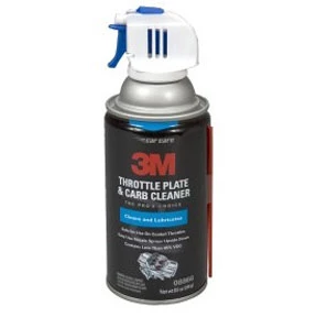

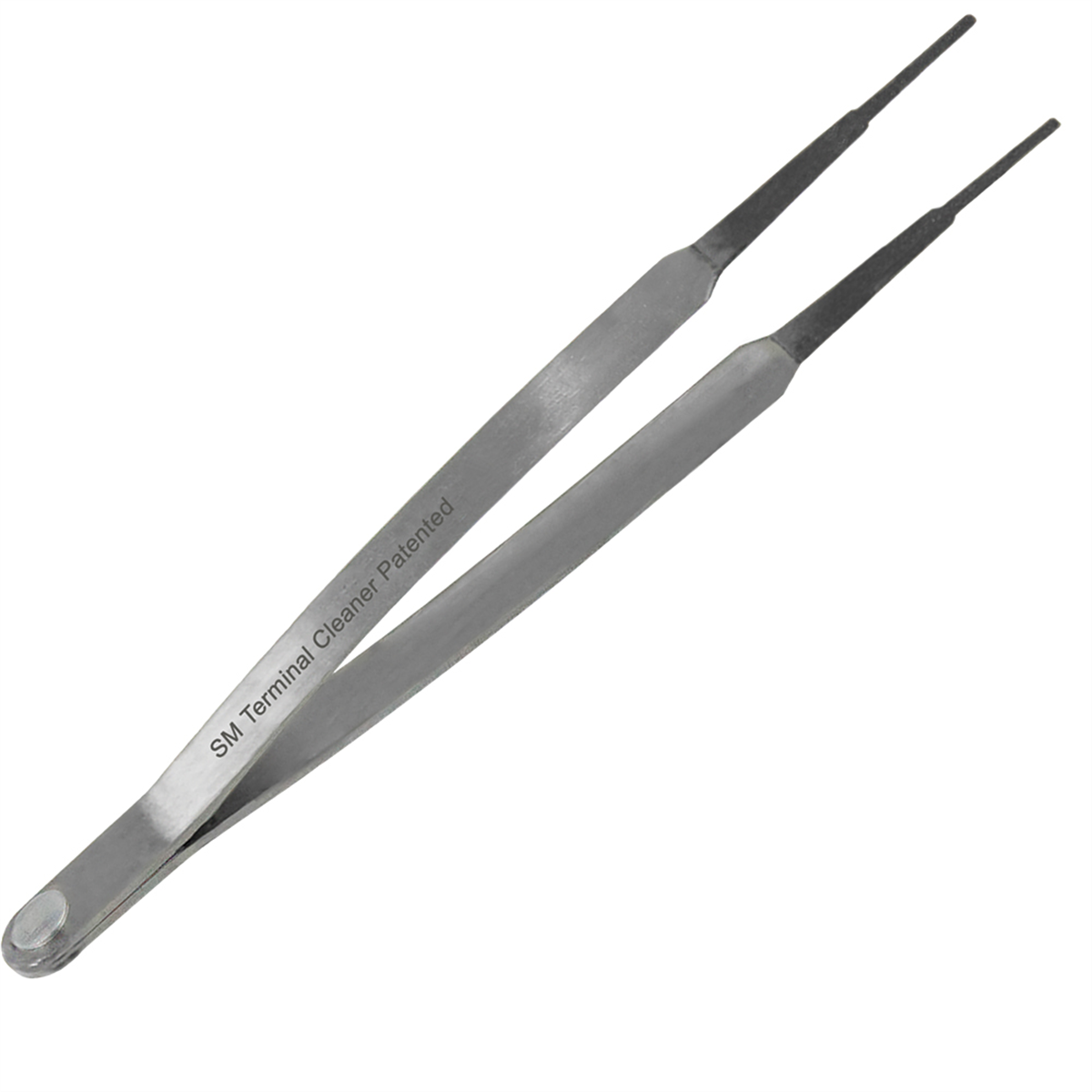
Small Terminal Cleaner for Electrical Connections 8040-S
Mfg: Innovative Products of America
Part #: 8040-S
Use only electronics-safe solvents. Never use carburetor or brake cleaner. Remove the sensor completely, spray electronics cleaner into the vacuum port (don’t disassemble), allow 15-20 minutes air drying, avoid compressed air, and never touch the sensing element. CRC and Johnsen’s make sensor-safe cleaners for this application.
Cost comparison: cleaning versus full replacement by vehicle type
| Vehicle Type | MAP Sensor Cost | Cleaning Cost | Labor (Replacement) | Recommended Approach |
|---|---|---|---|---|
| Domestic (GM, Ford, Chrysler) | $25-$65 | $8-$12 | $45-$75 (0.5-1.0 hr) | Replace if failed; clean only if contaminated |
| Asian (Honda, Toyota, Nissan) | $45-$95 | $8-$12 | $60-$90 (0.5-1.0 hr) | Clean first if accessible; replace if no improvement |
| European (BMW, Mercedes, VW) | $85-$180 | $8-$12 | $90-$150 (1.0-2.0 hr) | Always attempt cleaning first |
| Performance/Aftermarket | $65-$250+ | $8-$12 | Varies | Clean regularly as preventive maintenance |
For domestic vehicles where sensors cost $25-$40 and take 15 minutes to replace, cleaning provides minimal savings. For European vehicles where genuine sensors exceed $150, cleaning is worth attempting before replacement.
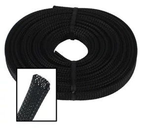
Impact on Engine Performance and Transmission
Faulty MAP sensors affect fuel delivery, engine management systems, and transmission operation.
How faulty MAP sensors cause rough idle and running issues
The ECU uses MAP sensor data to calculate engine load, which determines fuel injector pulse width. Incorrect readings cause incorrect fuel delivery. At idle, small MAP sensor errors cause noticeable roughness, engine hunting between 600-900 RPM, or stalling. Under acceleration, faulty sensors create hesitation or stumbling.
Transmission control module interaction and performance effects
Modern electronic transmissions share MAP sensor data between the ECU and transmission control module (TCM). The TCM uses engine load information for optimal shift points, torque converter lockup timing, and shift firmness. A sensor reading constant high load delays upshifts and holds lower gears, resulting in higher RPM cruising and reduced fuel economy. Constant low load causes premature upshifts and early lockup, resulting in lugging. According to Automatic Transmission Rebuilders Association, MAP sensor faults should be ruled out before diagnosing transmission problems.
Fuel injection and ignition timing problems from sensor faults
MAP sensors affect fuel injection timing on sequential port systems and ignition timing. A sensor stuck reading high vacuum causes over-advanced timing under acceleration (destructive knock), while a sensor stuck reading low vacuum causes retarded timing at cruise (reducing power and fuel economy). Modern engines with continuously variable valve timing use MAP data for cam phaser control, compounding performance issues.
MAP Sensor Diagnostic and Installation Checklist
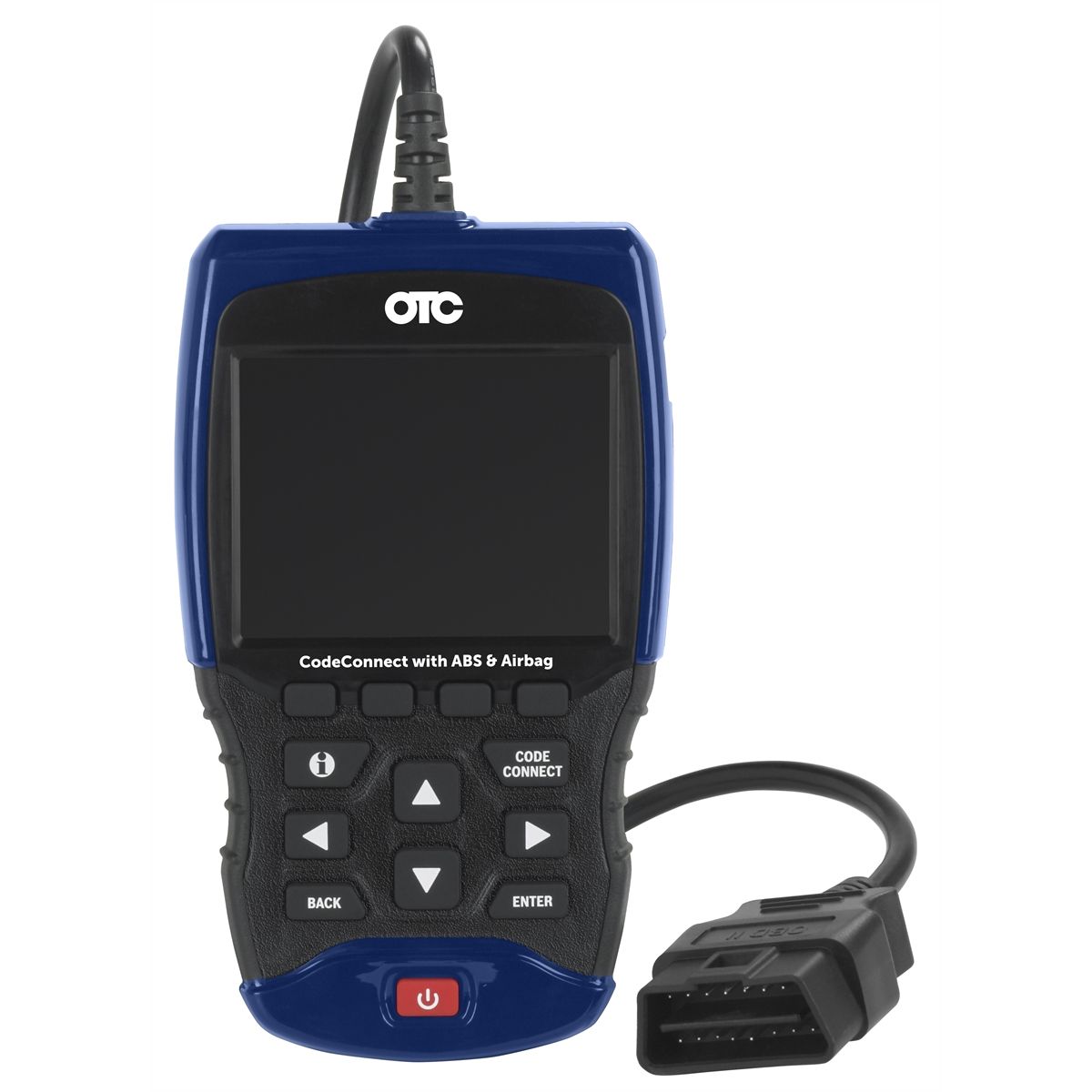
OBD2 Scanner with ABS, Airbag & CodeConnect Support
Mfg: OTC Tools and Equipment
Part #: 3210
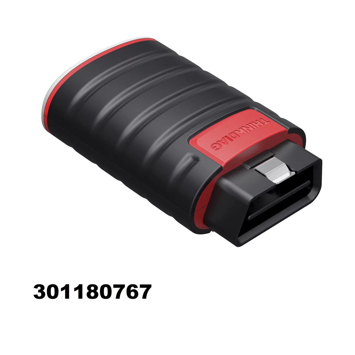
ThinkCar ThinkDiag Bluetooth OBD2 Scanner for DIY Auto Repair
Mfg: ThinkCar
Part #: 301180767

Pre-Diagnostic Checks:
- ☐ Verify you have a MAP sensor (not MAF) by visual identification
- ☐ Record all diagnostic trouble codes present in ECU
- ☐ Check for technical service bulletins related to MAP sensor or codes
- ☐ Verify air filter condition and intake system integrity
- ☐ Inspect all vacuum hoses for cracks, kinks, or disconnections
Electrical Testing:
- ☐ Test 5-volt reference supply (should be 4.8-5.2V)
- ☐ Test ground circuit resistance (should be under 0.1 ohms)
- ☐ Check signal voltage key-on-engine-off (should be 4.0-5.0V)
- ☐ Check signal voltage at idle (typically 1.0-2.0V, altitude dependent)
- ☐ Verify signal changes smoothly with throttle application
- ☐ Inspect connector for corrosion, bent pins, or water intrusion
Physical Inspection:
- ☐ Check sensor mounting for cracks or air leaks around O-ring
- ☐ Inspect vacuum hose connection for proper sealing
- ☐ Look for oil, carbon, or debris in vacuum port
- ☐ Verify sensor is mounted in appropriate location (near plenum/throttle body)
Installation Procedure:
- ☐ Compare new sensor part number to old sensor and verify compatibility
- ☐ Install new O-ring if applicable; do not reuse old O-ring
- ☐ Torque sensor to specification (typically 45-75 in-lbs; consult service manual)
- ☐ Apply dielectric grease to connector terminals before connection
- ☐ Secure vacuum hose with proper clamp if external sensor
- ☐ Clear diagnostic codes and verify no codes return
- ☐ Test drive and monitor live data to confirm proper operation
Frequently Asked Questions About MAP Sensors
Can I clean my MAP sensor myself, or should I replace it?
You can clean a MAP sensor using electronics-safe cleaner if it has visible contamination in the vacuum port and hasn’t completely failed electrical testing. For sensors that failed voltage tests or show constant out-of-range readings, replacement is necessary. Cleaning costs $8-$12 and takes 15 minutes, while replacement costs $25-$180 depending on vehicle make. For accessible, higher-priced sensors (European vehicles), attempting cleaning first makes financial sense.
Does a bad MAP sensor always require replacement?
No—P0107 and P0108 codes result in actual sensor replacement less than 40% of the time professionally. Remaining cases involve corroded connectors, damaged wiring, blocked vacuum hoses, poor ground connections, or ECU issues. Always perform complete circuit testing (5-volt reference, ground integrity, signal wire continuity) before replacing the sensor. Many apparent sensor failures are actually wiring or connector problems that cost nothing to repair.
What’s the difference between intake manifold design and sensor placement?
Manifolds with large central plenums provide naturally averaged pressure readings, so sensors can mount anywhere. Individual runner manifolds require sensors positioned near the throttle body or connected to multiple runners via Y-connectors. Never place sensors close to the cylinder head—this exposes them to excessive pressure fluctuations.
How does altitude affect MAP sensor readings?
Altitude directly affects readings since sensors measure absolute pressure, not vacuum. At sea level, key-on-engine-off readings should be approximately 4.5 volts (14.7 psi absolute). At 5,000 feet elevation, the same condition reads approximately 3.8 volts (12.2 psi absolute). The ECU compensates automatically using the key-on reading as barometric reference. When diagnosing, compare readings to altitude-adjusted specifications or use scan tool “expected” readings.
Can a MAP sensor cause transmission shifting problems?
Yes, on vehicles where the TCM uses MAP sensor data for shift scheduling and line pressure control. Constant high load causes delayed upshifts and harsh shifting; constant low load causes premature upshifts and slipping. However, not all vehicles share MAP data with the TCM—consult your service manual to determine if engine load information feeds transmission control before attributing shift problems to the MAP sensor.
Should I use an OEM MAP sensor or will aftermarket work?
Quality aftermarket sensors from Bosch, Delphi, and Standard Motor Products perform identically to OEM sensors at 30-50% lower cost for most domestic and Asian vehicles. European vehicles often require OEM sensors for better long-term accuracy, though quality aftermarket options work adequately. Avoid no-name sensors under $15—they often have poor calibration and fail within months. Match part numbers carefully, as many vehicles use different MAP sensors for different engine options.
Essential Tools for MAP Sensor Work
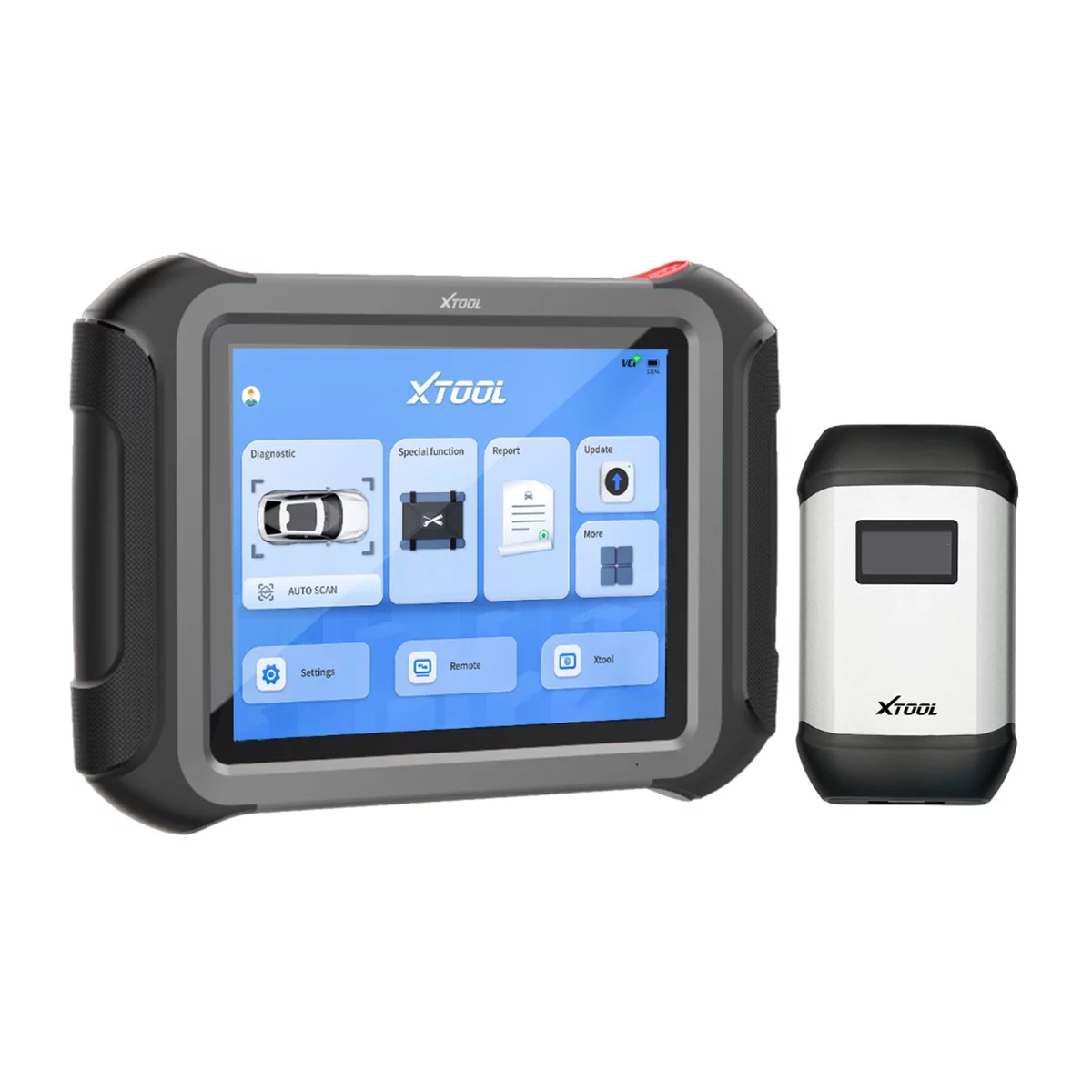
Once you’ve diagnosed a P0107 or P0108 error code, you’ll need the right tools to test and replace your MAP sensor. Our Other category stocks everything from diagnostic scanners to sensor replacement kits that make this job manageable even for DIY mechanics.
Browse our full selection of diagnostic and sensor tools:
- OBD-II Diagnostic Scanners – Advanced code readers to confirm P0107/P0108 faults and monitor sensor voltage in real-time
- Multimeters & Electrical Testing Tools – Verify MAP sensor output and wiring integrity before replacement
- Sensor Removal & Installation Kits – Specialized tools to safely extract and install MAP sensors without damaging connectors or ports
For the tools in this guide, browse A/C Manifold Gauges at Tool Source.

The Toolsource Technical Team blends decades of real-world automotive service experience with up-to-date technical research. Our writers collaborate with professional mechanics, shop owners, and diagnostic specialists to deliver practical, workshop-ready guidance you can trust.


Follow us on social media