
A dirty MAP sensor robs your engine of power and fuel economy without always triggering a check engine light. This sensor measures intake pressure to help your ECU calculate proper fuel delivery. When carbon deposits or oil contamination build up, you’ll notice rough idle, hesitation, and RPM fluctuations. Cleaning takes 5 minutes with the right approach, costs almost nothing, and restores lost performance immediately.
What is a MAP Sensor and Why It Gets Dirty
The Manifold Absolute Pressure (MAP) sensor measures pressure inside the intake manifold to determine engine load and help the ECU calculate the air-fuel ratio. It directly affects fuel injection timing, ignition advance, and overall performance.
MAP vs MAF sensor: key differences
A Mass Air Flow (MAF) sensor sits in the intake tube and measures actual airflow volume using a heated wire or film. The MAP sensor mounts on the intake manifold and measures pressure changes. Some vehicles use both for redundancy; turbocharged applications often rely primarily on MAP sensors because they measure both vacuum and boost pressure. MAF sensors are more susceptible to oiled air filter contamination, while MAP sensors get dirty from crankcase vapors and intake system contaminants. Cleaning procedures differ significantly—MAF sensors require specialized cleaner and extreme care, while MAP sensors are more robust.
How contamination occurs
Positive Crankcase Ventilation (PCV) vapor, which recirculates oily blow-by gases into the intake manifold, is the primary culprit. Oil droplets settle on the sensor and bake on due to engine heat, creating a varnish coating. Carbon deposits form when this residue contacts combustion gases. High-mileage vehicles, worn piston rings, and failing PCV valves accelerate contamination. Aftermarket oiled air filters can shed excess oil into the intake system, and aggressive catch can installations may introduce more contamination. Turbocharged engines push more crankcase vapor past seals, while direct injection engines lack fuel’s cleaning action on intake valves.
Performance symptoms
Rough or unstable idle with RPM fluctuations of 50-200 RPM is the most common symptom. Throttle response becomes sluggish with hesitation during light acceleration. Fuel economy typically drops 2-4 MPG. Some vehicles experience intermittent stalling when coming to a stop. Unlike a completely failed sensor, a dirty sensor provides readings within normal range but skewed enough to affect performance. Symptoms often worsen on cold starts and highway cruising.
Locating Your MAP Sensor
Common mounting locations
On naturally aspirated engines, the sensor is typically mounted directly on the intake manifold near the throttle body. Turbocharged applications may place it on intercooler piping or a dedicated manifold port. Subaru vehicles commonly mount it on the driver’s side near cylinder #1. Ford EcoBoost engines often integrate it into the manifold or position it on the firewall. GM vehicles frequently place it on top of the intake manifold with a vacuum hose connection. Honda and Acura models typically mount it on the firewall with a longer vacuum line. Consult your vehicle’s service manual or online forums for your specific make and model.
Visual identification
MAP sensors are small, roughly 2-3 inches long with a 3 or 4-wire electrical connector. The body is usually black or dark gray plastic with the manufacturer logo molded in. One end features the electrical connector with a locking tab; the other has either a vacuum port (small nipple) or a direct-mount flange with an O-ring. Don’t confuse it with the intake air temperature (IAT) sensor (smaller, 2 wires) or boost control solenoids (vacuum ports on both ends).
Tools needed
You’ll need an 8mm, 10mm, or T25 Torx socket/wrench for the mounting bolt, a screwdriver to release the connector locking tab, and pliers for vacuum hoses. For cleaning, use CRC Electronics Cleaner, CRC QD Electronic Cleaner, or 90%+ isopropyl alcohol. Have compressed air or an air compressor for drying. Optional items include nitrile gloves, a small container for runoff, lint-free cloth, and dielectric grease for connector maintenance.

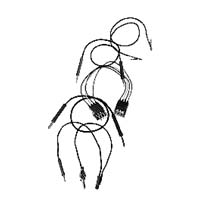
Extended Tyco and Bosch Duel Tab (Injector/Sensors)
Mfg: Thexton Toolworx LLC
Part #: 414517
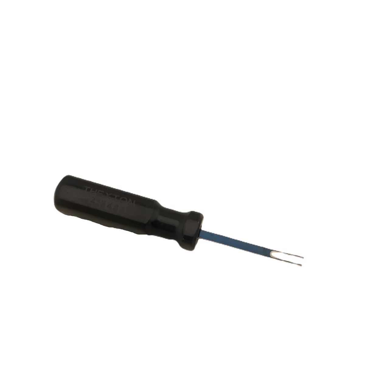
Micro Tyco and Bosch Duel Tab (Injector/Sensors)
Mfg: Thexton Toolworx LLC
Part #: 413483
Safe Cleaning Methods and Products
Approved cleaning solutions
CRC QD Electronic Cleaner and CRC Mass Air Flow Sensor Cleaner are the gold standards, formulated specifically for sensitive electronics. Isopropyl alcohol (91% or higher) is an excellent budget-friendly alternative that dissolves oil and carbon effectively while evaporating cleanly. Never use carburetor cleaner or brake cleaner—these harsh solvents dissolve internal components, melt plastic, or leave conductive residues. Avoid WD-40, which leaves an oily film.
| Product | Safety | Dry Time | Best Use |
|---|---|---|---|
| CRC QD Electronic Cleaner | Excellent | 60-90 sec | Professional-grade cleaning |
| Isopropyl Alcohol 91%+ | Excellent | 2-3 min | Budget option, soaking |
| MAF Sensor Cleaner | Excellent | 60-90 sec | Gentle, safe for all sensors |
| Brake/Carb Cleaner | Dangerous | 30 sec | NEVER USE—destroys sensor |
Step-by-step cleaning procedure
Disconnect the negative battery terminal. Photograph the electrical connector orientation and vacuum hose routing. Press the locking tab and carefully pull off the connector—never wiggle or twist. Gently remove the vacuum hose if equipped, using pliers if stuck. Remove the mounting bolt and extract the sensor. Hold it over a container and spray electronics cleaner liberally into the sensing port for 10-15 seconds. Rotate the sensor to drain excess cleaner and repeat from different angles. For heavy contamination, submerge the sensing end in isopropyl alcohol for 2-3 minutes. Use compressed air (40-50 PSI max) to blow through the sensor, forcing out liquid and loosened deposits. Air dry for 2-3 minutes—verify complete dryness. Never touch the internal sensing element with cotton swabs, brushes, or your fingers.
Why aggressive cleaning damages sensors
Brake cleaner’s harsh solvents attack the plastic housing, dissolve internal adhesives, and can damage the piezoelectric crystal or silicon diaphragm that forms the sensing element. Carburetor cleaner poses similar risks with strong hydrocarbons. Wire brushes, brass picks, and cotton swabs cause mechanical damage—the diaphragm is extremely thin (less than 0.001 inches) and can be punctured or torn by even gentle contact. Compressed air above 40-50 PSI can rupture the diaphragm. Sensors that “work” immediately after aggressive cleaning often fail within days as chemical damage progresses or small tears expand.
Reinstallation and Results
Proper reinstallation
Wipe the mounting surface on the intake manifold clean. If your sensor uses an O-ring, check it for cracks, hardening, or permanent deformation—replace if damaged. Apply a thin film of dielectric grease to the O-ring. Position the sensor correctly, engaging any alignment tabs. Thread the mounting bolt by hand first to prevent cross-threading, then tighten to 35-50 inch-pounds. Over-tightening cracks plastic threads. Reconnect the vacuum hose by pushing firmly onto the nipple. Inspect the electrical connector for bent pins before reconnecting. Push the connector straight on until the locking tab clicks. Tug gently to verify it’s locked.
Corrosion prevention
Inspect connector pins for green, white, or brown oxidation. Clean corrosion with electrical contact cleaner and a small wire brush, or remove and polish pins individually if necessary. Apply dielectric grease to each terminal to prevent moisture intrusion. Pay special attention to the ground wire terminal, as poor grounding causes voltage reference problems. For vehicles frequently exposed to salt, moisture, or extreme temperatures, wrap the connector with self-amalgamating tape for additional protection.
Performance improvements
Idle should stabilize within 30-60 seconds. Throttle response improves instantly. Fuel economy gains of 1-3 MPG materialize over the next 2-3 tanks. Some vehicles need 20-30 minutes of varied driving before the ECU fully adjusts. Use a scan tool to monitor MAP voltage at idle (should read 0.8-1.2V on naturally aspirated engines) and verify smooth response when blipping the throttle. Erratic voltage after cleaning indicates the sensor may be damaged or experiencing connector issues. If symptoms persist, verify vacuum hose integrity, check for manifold leaks, and consider the sensor may be electrically failed rather than simply dirty.

Maintenance Schedule and Prevention
Recommended cleaning intervals
Clean the MAP sensor every 10,000-15,000 miles for most vehicles under normal conditions. This aligns conveniently with oil changes. City driving, short trips, dusty environments, and performance modifications warrant more frequent cleaning every 5,000-7,500 miles. Highway-driven vehicles with minimal idling may extend to 20,000-25,000 miles. Watch for symptom development between intervals. Keep a maintenance log—patterns of rapid recontamination indicate underlying issues like PCV valve failure, excessive oil consumption, or air filter problems.
Catch cans and air filter upgrades
A properly installed catch can dramatically reduces contamination by intercepting oil vapor before it reaches the intake manifold. Quality catch cans reduce cleaning frequency by 50-75%, extending intervals to 20,000-30,000 miles on modified engines. However, improper installation can create crankcase pressure problems. Oiled cotton gauze air filters can shed oil droplets when over-oiled, accelerating contamination. Dry synthetic filters eliminate this concern. When installing performance parts, research your specific vehicle combination to minimize sensor contamination.
When to replace instead of cleaning
Replace the sensor if cleaning produces no improvement and readings remain erratic. Replace if there’s physical damage (cracked plastic, damaged vacuum nipples), corroded connector pins beyond cleaning, or broken retention tabs. Sensors contaminated with brake or carburetor cleaner should be replaced immediately. Sensors over 10-12 years old or with 200,000+ miles may have degraded internal components. If a sensor requires cleaning twice within 5,000 miles, address the underlying issue first (failed PCV valve, ring wear, turbo seal failure), then replace with a fresh unit. OEM sensors provide the best longevity; reputable aftermarket brands (Delphi, Bosch, Denso) are acceptable alternatives.
Frequently Asked Questions
Will a dirty MAP sensor trigger a check engine light?
A dirty MAP sensor rarely triggers a light directly because readings remain within expected voltage ranges—just inaccurate. However, incorrect readings causing improper fuel mixtures may trigger “System Too Rich” (P0172) or “System Too Lean” (P0171) codes. Severely contaminated sensors that stick at one reading may eventually trigger “MAP Sensor Circuit Range/Performance” codes (P0106-P0109).
Can I clean the sensor without removing it?
While technically possible, removal is strongly recommended for thorough cleaning. In-place cleaning prevents you from seeing the sensing element, doesn’t allow proper drainage of deposits, and risks contaminating the intake manifold. The time saved is minimal—removal takes 60-90 seconds. If access is extremely difficult, you can spray electronics cleaner into the vacuum port and sensor opening with the engine off, then use compressed air, but this approach is only 30-40% as effective.
OEM vs aftermarket sensors
OEM sensors meet exact factory specifications and provide the best longevity. Quality aftermarket sensors from reputable manufacturers provide 95-98% of OEM performance at 40-60% cost. Budget sensors may have lower-quality components, resulting in less accurate readings and shorter lifespan. For stock vehicles, quality aftermarket works fine; for modified or performance applications, OEM sensors provide consistency. Never buy used MAP sensors.
How do I know if cleaning worked?
Idle should stabilize immediately with smooth, consistent RPM. Throttle response becomes crisp. If you have a scan tool, MAP voltage at idle should be steady (0.8-1.2V typical) without erratic spikes, and increase smoothly when revving. If symptoms remain unchanged after cleaning and drying, the sensor may be internally failed, you have a separate issue (vacuum leak, PCV problem, MAF sensor issue), or connector corrosion affects the signal.
Related maintenance
When cleaning a MAP sensor, check the PCV valve operation (should rattle when shaken). Inspect vacuum hoses for cracks or hardening and replace if necessary. Clean or replace the air filter. Inspect the intake boot for cracks. Clean the MAF sensor simultaneously if equipped. Check the throttle body for carbon buildup. Verify no intake manifold gaskets are leaking by spraying carburetor cleaner around seams while idling—RPM changes indicate a vacuum leak.
Can a dirty MAP sensor cause transmission shifting problems?
Yes, indirectly. The transmission control module often receives engine load information from the ECU, which relies partly on MAP sensor data. Incorrect readings can cause delayed upshifts, harsh downshifts, or refusal to shift out of lower gears. However, this is less common than engine performance issues. Clean the MAP sensor first before pursuing expensive transmission diagnostics.
MAP Sensor Cleaning Checklist
- ☐ Gather tools: 8-10mm socket, electronics cleaner, compressed air, dielectric grease
- ☐ Locate MAP sensor and photograph electrical/vacuum routing
- ☐ Disconnect electrical connector by pressing locking tab
- ☐ Remove vacuum hose by twisting and pulling gently
- ☐ Remove mounting bolt and extract sensor
- ☐ Spray electronics cleaner through sensing port, rotate to drain
- ☐ Repeat spraying from multiple angles
- ☐ Blow through sensor with compressed air (40 PSI max)
- ☐ Air dry 2-3 minutes—verify no solvent smell
- ☐ Inspect and clean connector terminals for corrosion
- ☐ Check O-ring for damage and replace if necessary
- ☐ Reinstall sensor and hand-thread bolt to prevent cross-threading
- ☐ Tighten bolt to 35-50 inch-pounds
- ☐ Reconnect vacuum hose until fully seated
- ☐ Apply dielectric grease to connector terminals
- ☐ Reconnect electrical connector until locking tab clicks
- ☐ Start engine and verify smooth idle within 30-60 seconds
- ☐ Test drive and confirm improved performance
- ☐ Log cleaning date and mileage for future tracking
Extended Tyco and Bosch Duel Tab (Injector/Sensors)
Mfg: Thexton Toolworx LLC
Part #: 414517
Micro Tyco and Bosch Duel Tab (Injector/Sensors)
Mfg: Thexton Toolworx LLC
Part #: 413483
For the tools in this guide, browse Engine Leak Detectors at Tool Source.

The Toolsource Technical Team blends decades of real-world automotive service experience with up-to-date technical research. Our writers collaborate with professional mechanics, shop owners, and diagnostic specialists to deliver practical, workshop-ready guidance you can trust.


Follow us on social media