Resurfacing a flywheel is straightforward in the right hands, but small mistakes can create big problems: harsh engagement, chatter, premature clutch wear, or a comeback for vibration and noise. This guide walks through how to decide when to resurface versus replace, how to measure and maintain step height, best practices for machining, what to do with dual-mass flywheels (DMFs), and the reassembly checks that keep the job reliable.
When to Resurface vs Replace
Not every flywheel should be cut. Use the vehicle service information and a close inspection to make the call.
- Resurface a single-mass flywheel (SMF) when the friction surface shows glazing, light scoring, minor heat spotting, or unevenness that can be cleaned up within the minimum thickness/step height spec.
- Replace a flywheel if you see radial cracks, severe heat checking, loose ring gear teeth, chipped edges, heavy pitting, or if material removal needed to clean up would exceed service limits. If minimum thickness or step height cannot be maintained, replace.
- Use caution with dual-mass flywheels (DMFs). Most OEMs do not approve machining DMFs. They are tuned, balanced two-piece assemblies with internal springs and friction packs. If the DMF fails inspection (excess rotational freeplay, rock/wobble beyond spec, grease leakage, or heavy blueing), replace it. Only follow resurfacing procedures if the OEM or clutch supplier explicitly permits them and provides specs.
Quick note on rotors because it often comes up with flywheels: today’s thin, low-mass brake rotors frequently get replaced rather than cut due to minimal machineable material, cost, and time. If you machine rotors, verify minimum thickness, use an on-car lathe when possible to correct hub runout, and achieve proper surface finish. For flywheels, a dedicated flywheel grinder and correct step height replication are critical.
Prep and Measurements Before You Cut
The most common cause of post-resurface clutch issues is failing to maintain the flywheel’s original geometry. That means documenting the stack before you remove any material.
- Clean and inspect. Degrease, glass-bead the friction surface lightly if needed to reveal cracks (keep abrasive out of the pilot bore and ring gear). Remove rust from the pressure plate mounting land.
- Mark orientation. Index-mark the flywheel to the crank (if OEM guidance calls for it) and note any balance weights.
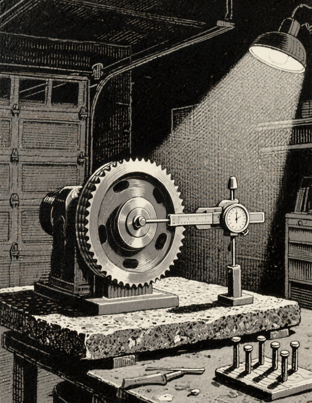
- Measure the step height. Using a depth micrometer, measure the height difference between the friction surface and the pressure plate mounting pads. Record multiple readings around the circumference and note the average. This dimension must be preserved.
- Check minimum specs. Consult OEM service information for minimum flywheel thickness and allowable runout after machining. If not provided, many passenger vehicles tolerate total indicated runout (TIR) ≤ 0.002–0.004 in (0.05–0.10 mm) at the friction surface, but always defer to OEM.
- Inspect and measure hot spots and grooves. Identify the deepest defect to estimate how much material removal will be required. Typical clean-up cuts on an SMF are 0.002–0.008 in (0.05–0.20 mm). If you need more than that, reevaluate whether to replace.
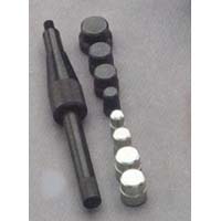
- Remove dowel pins (if required). If the pressure plate land will be cut to maintain the step, pull the locating dowels using a dowel puller or a collet-style slide hammer. Measure and record dowel height for reinstallation.
- Check pilot bearing/bushing. Spin and feel for roughness. Replace the pilot bearing or bushing as routine whenever the clutch is out.
Machining Best Practices (Single-Mass Flywheels)
Use a dedicated flywheel grinder for best results. A brake lathe or improvisation can alter geometry, leave torn grain, or overheat the part.
- Tooling and setup. Mount the flywheel on a proper arbor. Ensure it seats on clean, undamaged mounting faces. Indicate it to minimize runout before grinding.
- Coolant and feed. Use the grinder’s coolant as directed. Multiple light passes prevent thermal damage and maintain surface integrity.
- Cut the friction face. Make a clean-up pass and recheck. Continue with light passes until all heat spots and grooves are gone. Avoid dwelling; keep the stone moving uniformly to prevent localized hardening.
- Replicate the step height. Remove an equal amount from the pressure plate mounting land to match the material removed from the friction surface unless the OEM specifies a particular step dimension. Re-measure the step after machining and confirm you are within spec. This preserves clamp geometry and engagement point.
- Surface finish target. For organic friction materials, target ~40–60 µin Ra (≈1.0–1.5 µm). For many performance ceramic/metallic discs, a slightly rougher finish may be acceptable, but follow the clutch manufacturer’s recommendations. A uniform, fine crosshatch (30–45°) aids bedding.
- Deburr and chamfer. Lightly break the inner and outer edges to reduce stress risers. Deburr any bolt holes you dressed.
- De-magnetize (if equipped). Some grinders let you de-mag the part; this helps prevent debris attraction during assembly.
- Clean thoroughly. Hot wash, then brake-clean and dry the friction face. Any abrasive residue will contaminate the clutch.
- Reinstall dowels. Press dowel pins back to original height and verify fit with the pressure plate.
Verification matters as much as the cut. After machining, put the flywheel on a bench arbor, set up a dial indicator on the friction surface, and verify TIR at the outer diameter. If you can’t hold the runout target, check mounting faces for burrs, arbor fit, or warpage; replace if needed.
Dual-Mass Flywheels: Inspect, Don’t Guess
DMFs isolate drivetrain vibration using arc springs and friction elements between two flywheel halves. Their tuning and balance are specific to the engine and clutch package. Machining the friction face of only one half can change clamp geometry and risk imbalance; cutting both halves is not generally supported without factory specs and fixtures.
- Inspect rotational freeplay. Lock the primary mass and gently rotate the secondary mass; compare angular movement to OEM spec. Excess freeplay means the internal springs/friction pack are worn.
- Check for rock (tilt). Support the primary mass on a flat surface and attempt to rock the secondary mass. Any noticeable wobble beyond spec indicates worn bearings or rivets.
- Heat and contamination. Heavy blue/purple heat discoloration, grease leakage, or burnt odor are signs of distress. Replace the DMF.
- Balance and resurfacing. Unless OEM documentation permits a specific resurfacing procedure and step dimension, treat a marked or uneven DMF as replace-only. Remanufactured DMFs exist through specialty suppliers; follow their instructions strictly.
If you must install a new clutch on a borderline DMF, advise the customer that chatter or engagement issues are likely and document the measurement results. A failing DMF will damage a new clutch quickly.
Reassembly Essentials: Hardware, Clearances, Engagement Point
Most perceived “clutch problems” after resurfacing trace back to stack height changes, re-used hardware, or incorrect torque/sequence.
- Use new flywheel bolts if torque-to-yield (TTY). Many flywheel bolts are TTY. Replace and follow the torque + angle spec. Clean threads, verify hole depth, and use the specified thread treatment (dry, oil, or threadlocker) per service info.
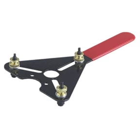
- Torque the flywheel in sequence. Stage torque in 2–3 steps in a star pattern with a flywheel holding tool. Verify crank flange is clean and burr-free.
- Install the clutch disc and pressure plate. Confirm disc orientation (trans side vs flywheel side). Use an alignment tool. Start all bolts by hand, then draw down evenly in a star pattern to the specified torque. Do not over-apply threadlocker if not specified.
- Verify stack height and release travel. If you resurfaced both the friction face and the pressure plate land equally, engagement point should remain close to original. Before closing the bellhousing, measure release bearing travel and verify the pressure plate fingers rise uniformly when actuated.
- Check bellhousing alignment and runout. On some applications, bellhousing misalignment induces clutch chatter. Use dowels and check input shaft pilot engagement. If specified by the OEM, check bellhousing concentricity and face runout.
- Replace related wear parts. Install a new release bearing/slave (CSC), pilot bearing/bushing, and inspect the fork, pivot ball, and hydraulic lines. Bleed hydraulics thoroughly to remove micro-bubbles that cause inconsistent release.
- Final fastener check. Verify pressure plate and flywheel torque, dowel seating, and that no harnesses or lines are pinched before reinstalling the transmission.
Post-Job Checks and Bedding
After installation, take time to prevent avoidable comebacks.
- Clutch break-in. Many organic clutches require a 300–500 mile (500–800 km) gentle break-in with minimal slip and no full-throttle launches. Follow the clutch supplier’s guidance.
- Driver technique matters. Excessive slipping, riding the clutch, or holding the vehicle on an incline with the clutch will quickly reintroduce hot spots, even on a freshly machined flywheel.
- Noise/vibration check. Listen and feel for chatter, judder, or shudder during takeoff. Recheck hydraulic bleed and verify mounts. If engagement is at the extreme top of pedal travel, re-check that step height was preserved.
- Final runout verification. If you have a driveline vibration complaint, verify crank/flywheel runout and clutch cover balance; some covers are indexed and must be aligned to dowels as marked.
Quick Technician Checklist
- Record original step height and note minimum thickness/runout specs.
- Plan to cut both the friction face and the pressure plate land by equal amounts (unless OEM step spec dictates otherwise).
- Target surface finish ~40–60 µin Ra for organic discs; clean thoroughly after grinding.
- Replace TTY flywheel bolts; torque and angle per spec.
- Install new pilot bearing/bushing and release bearing/CSC; bleed hydraulics completely.
- Verify clutch engagement point and release travel before final assembly.
FAQs
Q: How much material can I safely remove from a single-mass flywheel?
A: Only as much as needed to clean up defects while staying within OEM thickness, runout, and step height specs. Typical clean-up passes are 0.002–0.008 in (0.05–0.20 mm), but the allowable total removal depends on the specific flywheel and published limits.
Q: Do I have to machine the pressure plate mounting pads when I cut the friction surface?
A: Yes, unless the OEM provides a specific step dimension that changes. Removing material from only the friction face reduces clamp height and can move the engagement point toward the top of pedal travel, increase slip, and reduce clamp load. Match removal on the mounting pads to preserve the original step height.
Q: Can I hand-sand or use a makeshift setup to “resurface” a flywheel?
A: No. Hand sanding or improvised tools cannot produce the flatness, runout, or surface finish required. Use a dedicated flywheel grinder or a qualified machine shop with the right fixtures and experience.
Q: What surface finish should I target?
A: For most organic friction discs, a 40–60 µin Ra (≈1.0–1.5 µm) finish with a uniform 30–45° crosshatch is appropriate. Performance ceramic or metallic discs may specify different targets; follow the clutch manufacturer’s recommendations.
Q: Why did the clutch engagement point change after resurfacing?
A: The step height likely changed because only the friction surface was cut. Re-measure the difference between the friction face and the pressure plate mounting pads. If the step is smaller than spec, clamp geometry changed; the fix is to machine the mounting pads to restore the step, or replace the flywheel if the spec cannot be achieved.
Q: Are flywheel bolts always torque-to-yield?
A: Not always, but many modern applications use TTY fasteners for the flywheel. Consult service information. If TTY, replace and use torque + angle. Pressure plate bolts are commonly reusable if within spec, but follow OEM guidance and apply correct torque and thread treatment.
Q: What about dual-mass flywheels—can they be resurfaced?
A: Usually no. DMFs are balanced, tuned assemblies and most OEMs do not approve resurfacing. Inspect for freeplay, rock, heat damage, or grease leakage; if out of spec, replace. Only follow resurfacing procedures if explicitly provided by the manufacturer or a qualified reman supplier.
Q: My flywheel had hot spots—will they just come back?
A: Light to moderate heat spots that grind out within shallow removal typically do not return if the root cause is addressed (driver technique, hydraulic issues, dragging release, or a failing DMF). If hot spots are deep or accompanied by cracking, replace the flywheel.
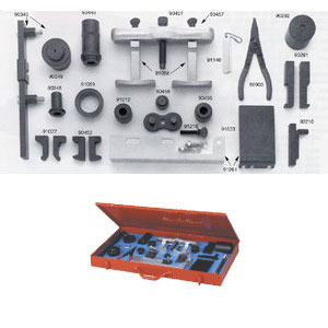
Shop Clutch & Flywheel Service Tools
For accurate resurfacing and reliable clutch engagement, see our clutch and flywheel service tools to measure step height, verify runout, and set up machining correctly.
- Depth micrometers and straightedges for step height checks
- Dial indicators and magnetic bases for TIR verification
- Flywheel holding and clutch alignment tools for clean reassembly
The Toolsource Technical Team blends decades of real-world automotive service experience with up-to-date technical research. Our writers collaborate with professional mechanics, shop owners, and diagnostic specialists to deliver practical, workshop-ready guidance you can trust.


Follow us on social media