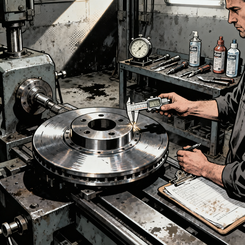
Every shop has seen it—a technician trying to save a customer money by resurfacing rotors with whatever tools are on hand. The recent case of a rotor “resurfaced” with a cutoff wheel and die grinder highlights a fundamental misunderstanding of how brake rotor machining works. While the effort might look passable to the untrained eye, this approach violates basic principles of rotor geometry and surface finish. The aggressive circular grooves left by hand tools create uneven contact with brake pads, leading to pulsation during braking, accelerated pad wear, and potential noise issues. Understanding why proper machining matters—and what actually constitutes acceptable rotor resurfacing—separates professional brake service from backyard shortcuts that compromise safety and performance.
Why Hand-Tool Rotor Resurfacing Fails: The Physics of Brake Contact
Brake rotors require two critical characteristics: parallel friction surfaces and consistent thickness throughout their rotation. A brake lathe achieves this by spinning the rotor at controlled speeds while a cutting tool removes material perpendicular to the rotor face. This creates a true, flat surface with minimal runout (lateral wobble) and consistent thickness measurements across the entire friction surface.
When you attack a rotor with a cutoff wheel or die grinder, you’re introducing multiple variables that destroy these requirements. First, maintaining even pressure by hand across the rotor surface is impossible—you’ll inevitably remove more material in some areas than others. Second, the aggressive grit pattern left by cutoff wheels creates deep grooves that run in the wrong direction. Instead of the fine, non-directional finish a lathe produces, you get circumferential scratches that cause the brake pads to “skip” across high spots during initial contact.
The result is predictable: brake pulsation as the caliper pistons get pushed back by thick spots in the rotor, uneven pad wear as material transfers primarily to the high points, and potential noise as the pads chatter across the irregular surface. One commenter noted their hand-resurfaced rotor had “ever so slightly minimal pulsation”—that’s the high and low spots the die grinder created, and it will only get worse as heat cycling exacerbates the unevenness.
Proper Rotor Resurfacing: Lathe Specifications and Runout Limits
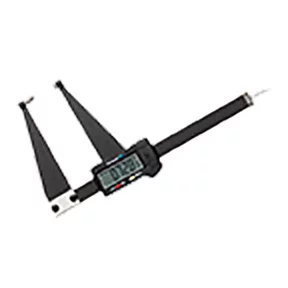
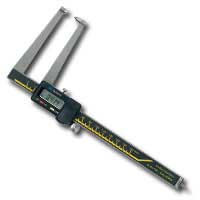
Professional rotor resurfacing requires a brake lathe and adherence to manufacturer specifications. Before mounting any rotor on a lathe, measure thickness at multiple points using a micrometer. Most rotors have minimum thickness specifications cast into the hub or hat section—typically expressed as “MIN TH” followed by a measurement in millimeters or inches. If the rotor is already at or within 0.030 inches (0.76mm) of minimum thickness, it cannot be safely resurfaced regardless of condition.
Once you’ve verified adequate material, mount the rotor on the lathe according to the machine’s instructions. Modern on-car and bench lathes use different mounting systems, but the principle remains the same: the rotor must be secured without introducing runout. Use a dial indicator to check lateral runout before cutting—acceptable runout is typically 0.002 inches (0.05mm) or less for most passenger vehicles, though performance applications may require tighter tolerances down to 0.001 inches.
The actual cutting process removes material in controlled passes, typically starting with a roughing cut of 0.010-0.015 inches per side, followed by a finishing cut of 0.003-0.005 inches. Modern brake lathes often include a non-directional finishing attachment—a disc or wheel that creates a crosshatch pattern on the rotor surface. This crosshatch (often mistaken by DIYers as something they can replicate with a grinder) helps new pads bed in properly by providing microscopic peaks and valleys that hold brake pad material during the initial break-in period.
After machining, re-measure thickness at multiple points around the rotor. Thickness variation should not exceed 0.0005 inches (0.013mm) for most applications. Clean the rotor thoroughly with brake cleaner to remove metal particles and protective oil, then re-check runout after installation on the vehicle. If runout exceeds specification after installation, the problem is likely with hub face cleanliness or wheel bearing condition, not the machining quality.


Identifying Rotors That Cannot Be Saved
Not every rotor is a candidate for resurfacing, even with proper equipment. Deep scoring—grooves you can catch a fingernail in—often requires removing too much material to clean up. Measure the depth of scoring with a depth gauge; if grooves exceed 0.060 inches deep and the rotor is already near minimum thickness, replacement is the only option.
Heat checking presents another common issue. These are the fine cracks that form on rotor surfaces exposed to repeated severe braking. Light heat checking (cracks less than 0.5 inches long that don’t extend to the edge or center of the friction surface) can sometimes be machined away, but extensive checking means the rotor has been heat-cycled beyond its metallurgical limits. The temper of the iron has changed, and even if you remove the visible cracks, the underlying material is compromised and prone to rapid re-cracking.
Warped rotors—more accurately described as rotors with thickness variation—can theoretically be resurfaced if enough material exists. However, thickness variation usually results from uneven pad deposits or localized overheating, conditions that indicate the rotor has been stressed. Many technicians simply replace warped rotors rather than machine them, knowing that once thickness variation develops, the rotor is more susceptible to repeat warping.
Check for hard spots by running a file across the friction surface. If the file skips over certain areas without cutting, those are hard spots—localized areas where extreme heat has changed the molecular structure of the iron. Hard spots cannot be machined away with conventional lathe tooling, and they’ll cause uneven pad wear and potential pulsation. Replace any rotor with significant hard spots.
The Economics of Rotor Replacement vs. Resurfacing
The declining cost of replacement rotors has fundamentally changed the resurfacing equation. Twenty years ago, quality replacement rotors cost significantly more than resurfacing, making lathe work economically justified. Today, aftermarket rotors for common vehicles often cost $30-50 each from discount suppliers, while resurfacing charges typically run $15-25 per rotor when outsourced to machine shops.
For shops with in-house brake lathes, the calculation includes labor time. Removing, measuring, mounting, machining, cleaning, and reinstalling a rotor takes 15-20 minutes per corner for an experienced technician. Compare that to the 5-minute swap of a new rotor, and the labor savings often exceed the cost difference between resurfacing and replacement—especially when you factor in the machine maintenance, cutting tool replacement, and shop space dedicated to lathe equipment.
Customer perception also matters. Many vehicle owners now expect new rotors with brake service, viewing resurfaced rotors as an inferior option. While properly machined rotors perform identically to new ones (assuming adequate thickness remains), explaining this to customers who’ve read online advice to “always replace rotors” creates unnecessary friction. Some shops have shifted to replacement-only brake service simply to eliminate this conversation.
That said, resurfacing still makes sense for premium vehicles with expensive OEM rotors, performance applications with specialized rotor metallurgy, and commercial fleet work where minimizing parts cost matters more than labor efficiency. The key is making the decision based on economics and rotor condition, not on the availability of hand tools in the toolbox.
Proper Pad Bedding After Rotor Service
Whether you’ve resurfaced or replaced rotors, proper pad bedding is critical for optimal brake performance. New or freshly machined rotors have different surface characteristics than worn rotors, and brake pads need a controlled heat cycle to transfer an even layer of friction material onto the rotor surface.
Start with 10-15 moderate stops from 40-45 mph, applying enough brake pressure to slow the vehicle noticeably but not enough to engage ABS. Allow 30-45 seconds between stops for cooling—don’t come to a complete stop and hold the brake pedal, as this can create pad material deposits on the hot rotor surface. You’ll often smell the brakes during this process; that’s normal as pad binders and surfacing agents burn off.
Follow with 5-8 harder stops from 50-55 mph, using firmer pedal pressure but still avoiding ABS activation. Again, keep the vehicle moving between stops or come to a complete stop and immediately release the brake pedal. After the final hard stop, drive for several minutes without using the brakes to allow thorough cooling.
Avoid heavy braking for the first 200-300 miles after rotor service. The pad-to-rotor interface continues to develop during this period, and aggressive braking before full bedding can create uneven material transfer that leads to pulsation issues later. For performance vehicles or aggressive driving conditions, consider using specific bedding procedures recommended by the pad manufacturer, as performance friction materials often require more extensive heat cycling.
What to Do When You’re Stuck with Improvised Rotor Work
If you’ve already attempted hand-tool resurfacing (or inherited a vehicle where someone else did), assess the damage with measurements, not hopes. Mount a dial indicator and check runout—if it exceeds 0.003 inches, the rotor will cause pulsation and should be replaced. Measure thickness variation with a micrometer at 8-12 points around the rotor; variation beyond 0.001 inches will create pedal pulsation.
For marginal cases where runout and thickness are acceptable but surface finish is rough, you can attempt to improve the situation with careful sanding. Mount the rotor on the vehicle, rotate it with the wheel studs using a socket and breaker bar, and apply 180-grit sandpaper evenly across the friction surface. This won’t fix thickness variation or runout, but it can knock down the worst of the hand-tool marks and reduce initial pad wear. Follow with 220-grit for a smoother finish.
Monitor the vehicle closely for the first 100 miles. If pulsation develops or worsens, if noise becomes excessive, or if you notice rapid pad wear (visible thickness loss after a few hundred miles), stop compromising and install proper replacement rotors. The $40 you saved on parts isn’t worth the customer complaint, comeback, or potential safety issue if the rotor fails catastrophically.
Quick Reference Checklist: Rotor Service Decision Tree
- Measure current thickness at 6-8 points with micrometer; if within 0.030″ of minimum spec, replace
- Check runout with dial indicator; if over 0.002″, investigate hub/bearing condition before resurfacing
- Inspect for heat checking; cracks extending to edges or longer than 0.5″ require replacement
- Test for hard spots with file; skipping indicates localized overheating and rotor should be replaced
- Assess scoring depth; grooves deeper than 0.060″ usually require too much material removal
- Compare costs; if replacement rotor is within $15 of resurfacing cost, replace for warranty and efficiency
- Machine properly if resurfacing; use calibrated brake lathe, not hand tools or bench grinders
- Verify final thickness and runout after machining; re-measure thickness variation under 0.0005″
- Clean thoroughly with brake cleaner to remove oils and metal particles before installation
- Follow bedding procedure with moderate stops followed by harder stops; avoid heavy braking for 200+ miles
Frequently Asked Questions
Can I resurface rotors that were previously turned?
Yes, if adequate thickness remains. Measure carefully—each resurfacing removes material from both friction surfaces. If the rotor is within 0.030 inches of minimum thickness, replacement is safer than attempting another cut. Most rotors can be resurfaced 1-2 times over their service life before reaching minimum thickness limits.
Why does my brake pedal pulsate after new pads on old rotors?
Pulsation indicates thickness variation in the rotor—uneven thickness creates high and low spots that push the caliper piston back as the rotor rotates. This can result from uneven pad deposits, warping from heat, or simply wear patterns that developed over time. The rotor needs proper resurfacing or replacement to eliminate pulsation.
How can I tell if my shop properly resurfaced my rotors?
Properly machined rotors should have a consistent finish pattern across the entire friction surface, no visible grooves or chatter marks, and smooth braking without pulsation after proper bedding. Ask if they measured final thickness and runout—professional shops document these measurements. If braking feels rough or noisy immediately after service, the work may have been inadequate.
Is it safe to resurface only one rotor on an axle?
While not ideal, resurfacing one rotor is acceptable if the other is new or recently replaced and both rotors end up with similar thickness. However, rotors should always be replaced in axle pairs to maintain even braking characteristics. Mixing a heavily worn rotor with a freshly machined one on the same axle can cause brake pull.
What causes those grooves that look like record player tracks on rotors?
Circumferential grooves result from debris caught between the pad and rotor—often a rock, piece of pad backing plate, or metal contamination. These grooves cannot be fixed by pad replacement alone; the rotor must be resurfaced or replaced. Continuing to drive with grooved rotors accelerates pad wear and can damage calipers.
Do slotted or drilled rotors need special resurfacing procedures?
Slotted rotors can be resurfaced on a standard brake lathe if thickness permits, though the slots may become shallower. Drilled rotors generally cannot be resurfaced—the holes are typically too close to minimum thickness specs, and machining removes the chamfered edges that prevent crack propagation from the holes. Replace drilled rotors when worn.
Invest in Proper Equipment
Resurfacing rotors correctly requires a calibrated brake lathe—not a die grinder or cutoff wheel. If your shop is still relying on hand tools for rotor work, upgrading to dedicated brake system lathes will improve job quality, reduce comebacks, and streamline your workflow.
- Professional-grade lathes deliver the precise control needed for consistent thickness and runout
- Proper equipment pays for itself through fewer customer complaints and faster turnaround times
- Modern lathes include non-directional finishing attachments that create the crosshatch pattern hand tools cannot replicate
The Toolsource Technical Team blends decades of real-world automotive service experience with up-to-date technical research. Our writers collaborate with professional mechanics, shop owners, and diagnostic specialists to deliver practical, workshop-ready guidance you can trust.


Follow us on social media